


CHAPTER 7 HARDWARE SPECIFICATIONS
User's Manual U13502EJ2V0UM00
82
•
PG-FP3 pins not wired
Keep in mind the following points:
•
Open the CLK signal of the PG-FP3 to supply a clock to the microcontroller from the target.
•
Open the SCK signal when using a UART.
•
Open the SO signal when using IIC.
•
Open the HS signal when
not using
SIO + handshaking.
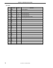
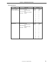
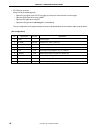
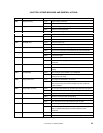
The pin configuration of the target interface connector and specifications of the interface cable are given below.
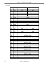
[Pin configuration]
Pin Signal name IN/OUT Specification
1GND
−
Common signal
2 SI (RxD) IN/OUT Serial data I/O (3-wire, UART, IIC)
3 SO (TxD) OUT Serial data output (3-wire, UART)
4 SCK OUT Serial clock output in 3-wire, IIC mode
5 CLK OUT Clock output to target (Select 16, 8, 4, or 2 MHz.)
6 _RESET OUT RESET signal output to target (Low: RESET ON)
7V
DD
IN/OUT V
DD
input/output to target (Select I/O with select switch.)
8V
PP
OUT V
PP
output to target
9 HS OUT Handshaking signal output of 3-wire + handshaking communication