


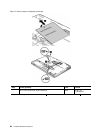
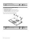
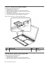
Table 20. Removal steps of BDC-2 (continued)
1
M2 × 4 mm, bind-head, nylon-coated (1)
Black 0.181 Nm
(1.85 kgfcm)
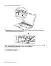
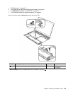
When installing: Make sure that the connector is attached rmly.
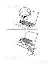
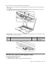
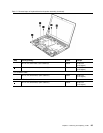
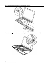
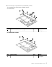
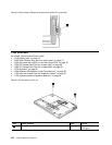
1120 Keyboard bezel and speaker assembly
For access, remove these FRUs in order:
• “1010 Battery pack” on page 75
• “1020 Serial Ultrabay Slim device or travel bezel” on page 75
• “1030 Solid state drive (SSD) or hard disk drive (HDD)” on page 76
• “1070 Keyboard” on page 85
• “1100 Palm rest or palm rest with ngerprint reader” on page 91
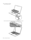
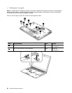
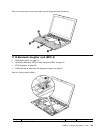
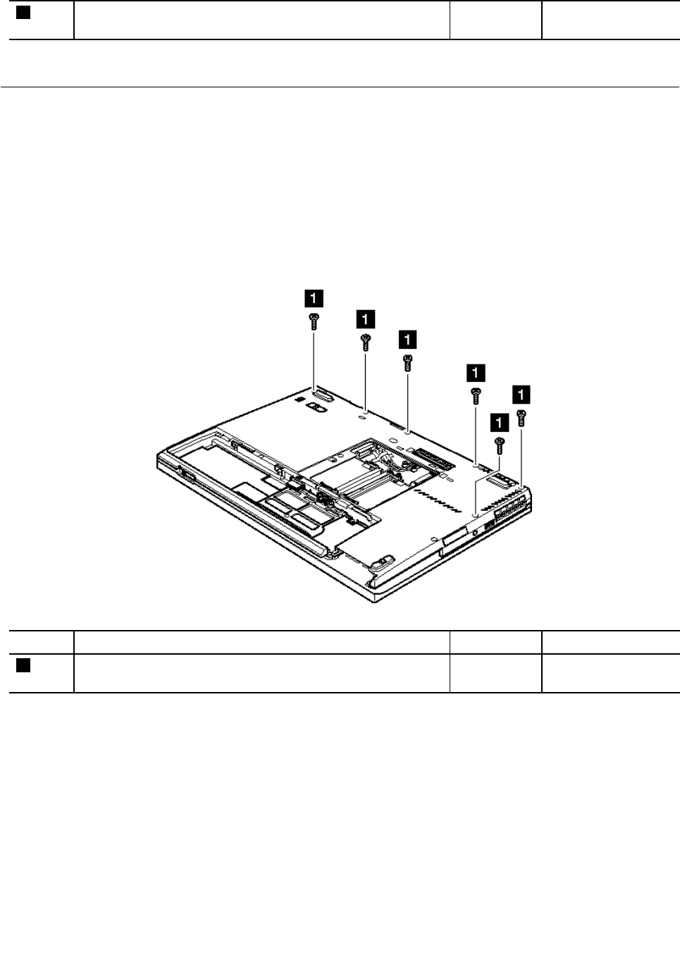
Table 21. Removal steps of keyboard bezel and speaker assembly
Note: The speaker assembly is attached to the keyboard bezel.
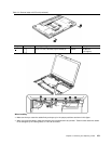
Step Screw (quantity) Color
Torque
1
M2 × 6 mm, bind-head, nylon-coated (6)
Black 0.181 Nm
(1.85 kgfcm)
94 Hardware Maintenance Manual