


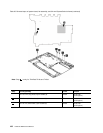
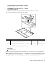
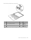

Table 25. Removal steps of system board, fan assembly, and 34-mm ExpressCard slot frame (continued)
For ThinkPad T410s and T410si:
Step Screw (quantity) Color
Torque
8
M2 × 3 mm, small−head, nylon-coated (2)
Black 0.181 Nm
(1.85 kgfcm)
9
M2 × 5 mm, at−head, nylon-coated (2)
Black 0.181 Nm
(1.85 kgfcm)
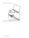
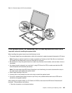
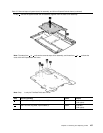
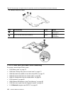
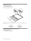
Turn the system board over, and then remove the 34-mm ExpressCard slot frame from the system board.
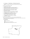
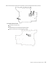
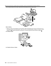
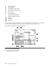
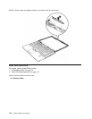
1170 I/O sub card and base cover assembly
For access, remove these FRUs in order:
• “1010 Battery pack” on page 75
• “1020 Serial Ultrabay Slim device or travel bezel” on page 75
• “1030 Solid state drive (SSD) or hard disk drive (HDD)” on page 76
• “1050 PCI Express Mini Card for wireless LAN” on page 80
• “1060 PCI Express Mini Card for wireless WAN” on page 83
• “1070 Keyboard” on page 85
• “1090 Wireless USB adapter or Intel Turbo Memory” on page 90
• “1100 Palm rest or palm rest with ngerprint reader” on page 91
• “1110 Bluetooth daughter card (BDC-2)” on page 93
110 Hardware Maintenance Manual