UDAS-1001E Series Data Acquisition Systems
1-6
If an analog input is used for the trigger, specify the trigger level, analog input channel, and
slope. Use analog output channel 1 for setting the trigger level.
When an input signal on the selected channel of the proper slope (rising or falling voltage) crosses
the trigger level, the conversion process begins.
Stopping Conversions
To stop a conversion, use either a software command, an N samples counter, or a combination of a
trigger and an N samples counter.
Use the N samples counter to specify the number of samples that you want to capture.
When the trigger is used to stop a conversion, and the N samples counter is used, a post-
triggering function occurs. In this mode, software is used to start conversions and continue
indefinitely until a trigger event occurs. When a trigger event occurs, N additional samples are
captured.
Rate GeneratorRate Generator
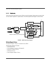
The UDAS unit contains an on-board 24-bit rate generator for analog input pacing. The base clock
for the rate generator is an 8 MHz clock derived from a crystal which provides 125 ns resolution
and a frequency range of 0.4768371 Hz to 4 MHz.
The I/O connector has a rate generator output pin that is driven by either the Analog Input Rate
Generator or the Analog Output Rate Generator.
Channel ScannerChannel Scanner
When the channel scanner is enabled, immediately after the conversion on the current channel
finishes, the next analog input channel to be converted is automatically selected.
The UDAS device incorporates a 0 to N scanner. This allows analog conversions on all of the input
channels from channel 0 to channel N, where the value of N is programmable.
The scanner selects each channel for conversion, beginning with channel 0, incrementing to
channel N. After the conversion on channel N is complete, the scanner selects channel 0 and the
process repeats.
Note: When using analog input channel 1 for a trigger, do not use this channel
for any other purpose.


