Analog Input and Output Calibration Procedures
C-6
C.2C.2 UDAS Analog Output Circuit Calibration UDAS Analog Output Circuit Calibration
ProcedureProcedure
This section applies to models UDAS-1001E-2, UDAS-1001E-2G, and UDAS-1001E-4 that are
equipped with the analog output feature.
The analog output channels on the UDAS unit are calibrated at the factory. If your application
requires periodic calibration checks or if you suspect inaccuracies, use the following procedures to
calibrate the unit. This calibration is accomplished by adjustment of potentiometers on the unit’s
printed circuit board.
Equipment Required:
• Precision Voltmeter accurate to 100 µV over a range of ±10 V.
• Termination panel for connecting signals and test instruments.
• 1.4 mm flat-head insulated screwdriver for adjusting potentiometers.
• #1 Phillips screwdriver and a small wrench or nut driver for opening the unit’s case.
• USB equipped host computer.
Instructions for opening the unit’s case are listed at the beginning of section C.1.1 Removing the
UDAS Unit’s Cover on page C-1.
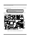
Connect the UDAS to the host computer and allow at least a 15 minute warm-up period before
making any adjustments. See FIGURE C.1 Locations of Potentiometers for Adjusting Analog
Circuits on page C-2.
Note: This calibration procedure requires the utility software provided with the unit, or
some other software such as Visual Designer for setting the Analog Output levels.
CAUTION:
STATIC SENSITIVE DEVICE WARNING! To avoid damage to the unit from static
electricity, always use proper static protective procedures (such as use of a grounded
wrist strap) when handling or adjusting this device.
CAUTION:
The unit may become damaged if you use an uninsulated screwdriver and accidentally
touch other components.


