


C-7
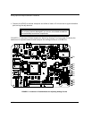
Analog Output Channel 0 Offset and GainAnalog Output Channel 0 Offset and Gain
1. Verify the termination panel is attached to a 50-pin connector of a UDAS unit. Begin with step
2 if the unit has built-in termination.
2. Attach a multimeter to analog output channel 0.
3. Use SYSCHECK or other software to set analog output channel 0 to -10.000 V.
4. Adjust Pot R26 for -10.000 V (±0.2 mV).
5. Set analog output channel 0 to 9.9951 V.
6. Adjust Pot R36 for 9.9951 V (±0.2 mV).
7. Repeat these steps to verify the results.
Analog Output Channel 1 Offset and GainAnalog Output Channel 1 Offset and Gain
1. Verify the termination panel is attached to a 50-pin connector of a UDAS unit.
2. Attach a multimeter to analog output channel 1.
3. Use SYSCHECK or your calibration software to set analog output channel 1 to -10.000 V.
4. Adjust Pot R24 for -10.000 V (±0.2 mV).
5. Set analog output channel 1 to 9.9951 V.
6. Adjust Pot R25 for 9.9951 V (±0.2 mV).
7. Repeat these steps to verify the results.