


©2001 Inova Computers GmbH Page B-3CPU Appendix-B
Appendix B
ICP-HD
CompactPCI
®
B
J13A
J10A
J9A
J11
J13
J9
J10
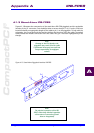
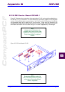
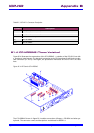
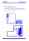
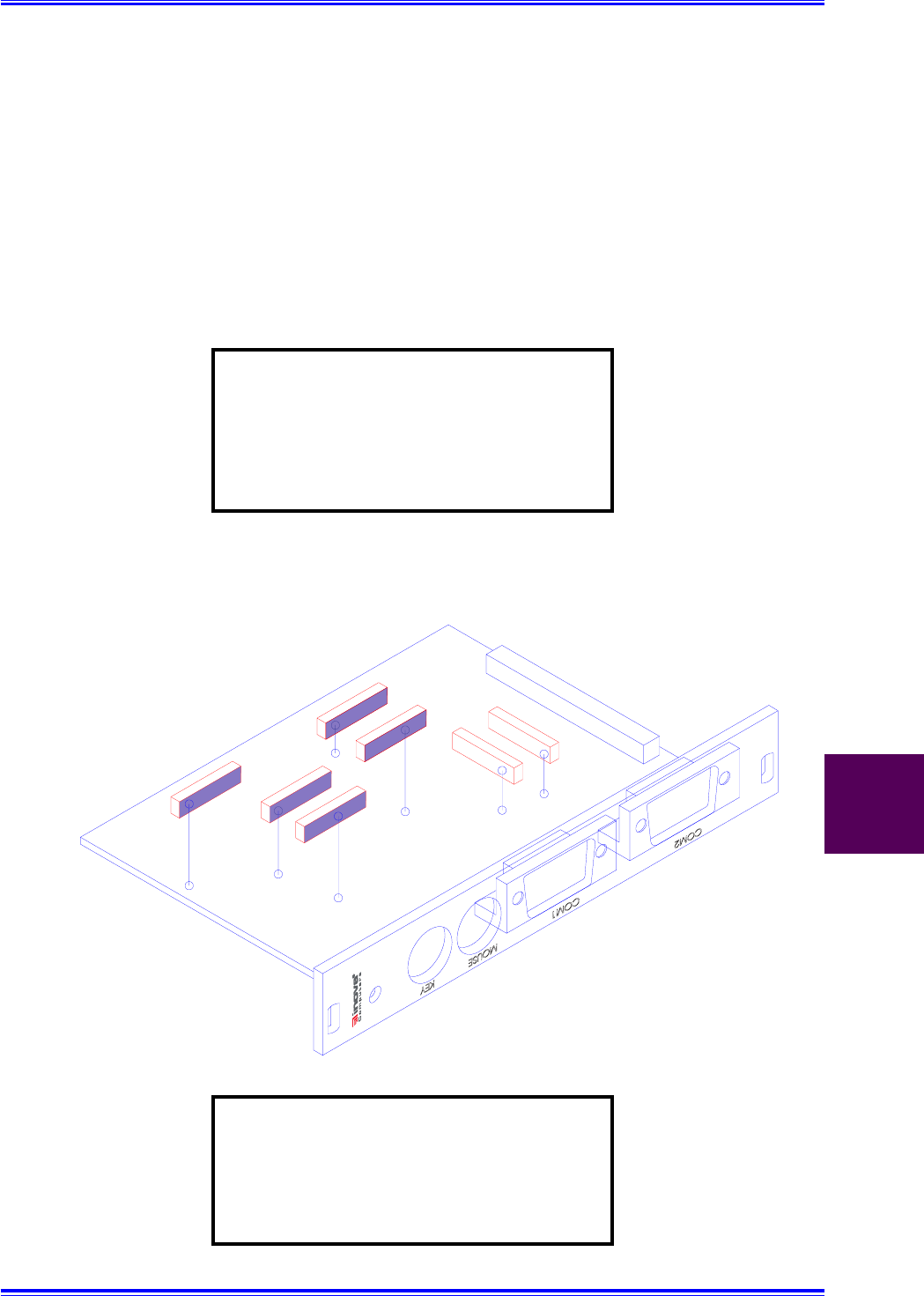
B1.3 IDE Carrier Board ICP-HD-1
Figure B1.3 illustrates the construction of the stand-alone ICP-HD1 carrier and the underside loca-
tion of the J11 & J13 connectors. The same mechanical construction applies to the integrated
version. Care should be taken to ensure that pin 1 of J11/J13 on the CPU base board is linked by
an appropriate length of flex cable to pin 1 on the carrier. To help with the orientation, the
connector flanks that are blue indicate the blue face of the flex-cable. Unmarked flanks indicate
the metallic connection of the flex-cable. Also, pin 1 has been highlighted by a red triangle.
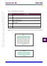
Note:
Damage to the CPU board or the
piggyback may result if the flex cable
is positioned incorrectly. Inova will not
accept responsibility for negligent
actions!
Figure B1.3 IDE Carrier Board ICP-HD1
Note:
The physical connection of the ICP-
HD-1 is electrically identical regardless
of the nature of connection (stand-
alone or integrated!)