


©2001 Inova Computers GmbH Page B-5CPU Appendix-B
Appendix B
ICP-HD
CompactPCI
®
B
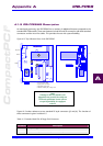
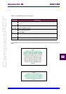
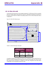
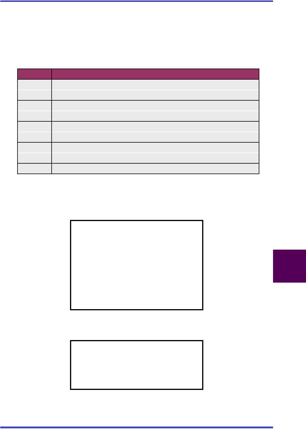
* If connectors 9 and 10 are connected to a Master device then 9a and 10a must be connected to a
Slave.
Connector Description
J1 Standard Floppy Disk Connector - To Floppy Disk
J2 Standard IDE Connector - To Hard Disk / FLASH
J9, J10 Primary HD (Master / Slave)
J9a, J10A Primary HD (Master / Slave)
J11 COM1, Mouse & Keyboard
J13 LPT1 & COM2
J13A LPT1 & COM2*
J18 Slim-Line Floppy Disk Connector - To CPU Base Board
J18A Slim-Line Floppy Disk Connector - To Floppy Disk
Table B1.4 IPB-HDE8MS Connector Description
Note:
* Tables B1.3 and B1.4 refer to J13
and J13a for the connection of COM2
and LPT1. Both the ICP-HD-1 and ICP-
HDE8 possess COM2 which is accessed
through J13 connected to the CPU
board. If the Inova IPB-FPE12 piggy-
back is used and connected to J13a
then the COM2 on the IDE carriers
ICP-HD-1 and ICP-HDE8MS will be
disabled.
Note:
Damage to the CPU board or the
piggyback may result if the cables are
incorrectly positioned. Inova will not
accept responsibility for negligent
actions!