©2001 Inova Computers GmbHPage B-6 CPU Appendix-B
IPM-ATA
Appendix B
B1.4 IPM-ATA-PCMCIA
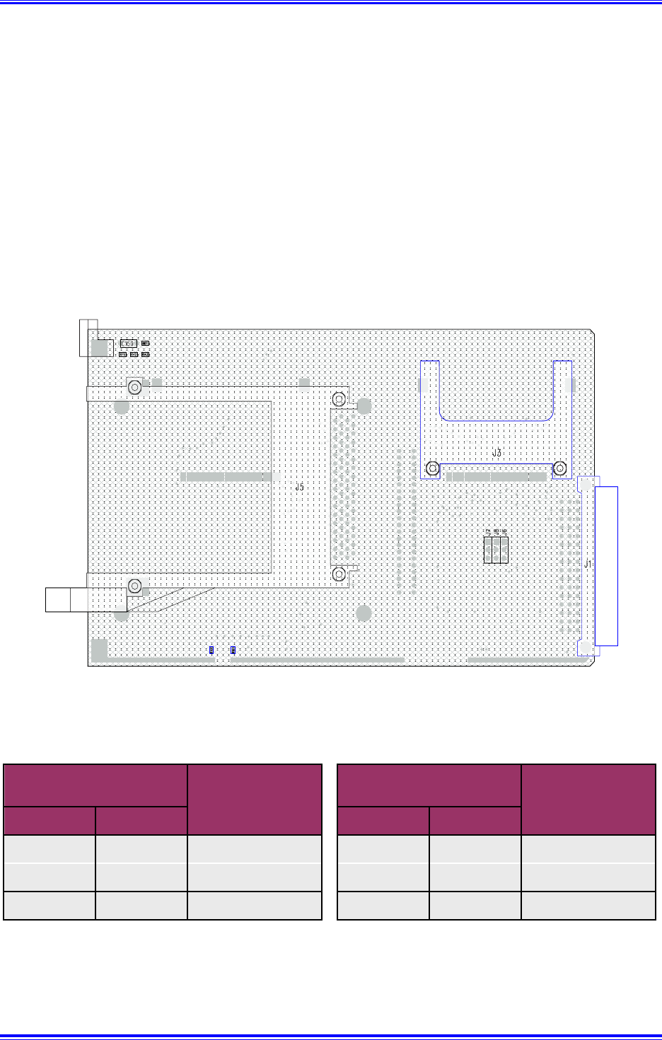
The IPM-ATA-PCMCIA has provision for one standard ATA PCMCIA device and one Compact
FLASH or MicroDrive site. Figure B1.4 illustrates the significant connectors for this device while
Table B1.4 indicates the jumper settings for the various Master/Slave device configurations.
Figure B1.4 IPM-ATA-PCMCIA Board Layout
1
2
3
Table B1.4 IPM-ATA-PCMCIA Jumper Description
It should be noted that the secondary IDE channel only is available for use by the IPB-ATA-PCMCIA
(the primary is on the CPU board itself). A Master device must be present either in the form of an
external hard-disk, PCMCIA device, Compact FLASH, MicroDrive or CD-ROM etc. Slave only con-
figurations and multi Master configurations are not supported and will not work!
Master Slave Master Slave
X - 2-3 X - 2-3
- X Open - X Open
-- - -- -
Jumper J8
PCMCIA Device in J5
Compact FLASH
or MicroDrive in J3
Jumper J6


