


Motherboard Description
31
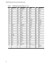
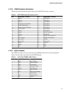
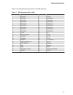
Table 17 lists the pinout and signal names for the IDE connectors.
Table 17. IDE Connectors (J8H1, J9H2)
Pin Signal Name Pin Signal Name
1 Reset IDE 2 Ground
3 Host Data 7 4 Host Data 8
5 Host Data 6 6 Host Data 9
7 Host Data 5 8 Host Data 10
9 Host Data 4 10 Host Data 11
11 Host Data 3 12 Host Data 12
13 Host Data 2 14 Host Data 13
15 Host Data 1 16 Host Data 14
17 Host Data 0 18 Host Data 15
19 Ground 20 Key
21 DDRQ0 (DDRQ1) 22 Ground
23 I/O Write# 24 Ground
25 I/O Read# 26 Ground
27 IOCHRDY 28 Vcc pull-down
29 DDACK0 (DDACK1)# 30 Ground
31 IRQ14 (IRQ15) 32 Reserved
33 DAG1 34 Reserved
35 DAG0 36 DAG2
37 Chip Select 1P (1S)# 38 Chip Select 3P (3S)#
39 Activity# 40 Ground