61
Drivers and/or the OS can detect the installed devices and determine resource consumption using the
defined PCI, legacy PnP BIOS, and/or ACPI BIOS interface functions.
8.3.4 Legacy ISA Configuration
Legacy ISA add-in devices are not supported by these platforms.
8.3.5 Automatic Detection of Video Adapters
The BIOS detects video adapters in the following order:
Offboard PCI
Onboard PCI
The onboard (or offboard) video BIOS is shadowed, starting at address C0000h, and is initialized before
memory tests begin in POST. Precedence is always given to offboard devices.
8.4 Console Redirection
Console redirection allows users to monitor the cPB-4612’s boot process and to run the cPB-4612’s
Setup utility from a remote serial terminal. Connection is made either directly through a serial port or
through a modem.
The console redirection feature is most useful in cases where it is necessary to communicate with a
processor board, such as the cPB-4612, in an embedded application without video support.
The BIOS supports redirection of both video and keyboard via a serial link (COM 1 or COM 2). When
console redirection is enabled in BIOS setup, local (host server) keyboard input and video output are
passed both to the local keyboard and video connections, and to the remote console via the serial link.
Keyboard inputs from both sources are considered valid and video is displayed to both outputs.
Optionally, the system can be operated without a host keyboard or monitor attached to the system and
run entirely via the remote console. Setup and any other text-based utilities can be accessed via console
redirection.
8.5 System Management BIOS (SMBIOS)
The cPB-4612 follows the criteria outlined in the System Management BIOS Reference Specification,
Version 2.3. Refer to this specification for details on SMBIOS.
8.6 POST CODE LEDS
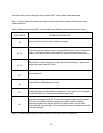
Four surface-mounted LEDS are located on cPB-4612 that indicate the post/board status. The LEDS are
arranged from the most significant bit (MSB) to the least significant bit (LSB), and a color scheme is used
to identify the bit values. For instance, the LED will be lit RED when one of the upper four bits is high and
will be lit GREEN when one of the lower bits is high. The upper and lower bits will be represented
simultaneously by the LEDS. Thus, the LED will appear ORANGE if one of the upper and lower bits is
both high in the same bit location. These eight bits represent a binary number, and if that binary number
is converted into a hexadecimal number you’ll have the failing code if the board fails to boot. An example
illustrating this is provided below.
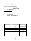
LED Color Description
R=RED G=GREEN O=ORANGE F=OFF
Bit in the upper nibble is high:
POST CODE 20 --- BIT values (MSB to LSB) 0010 0000
I I
Upper Nibble Lower Nibble


