Intel® Xeon® Processor E5-1600/E5-2600/E5-4600 Product Families 181
Datasheet Volume One
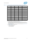
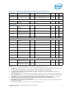
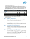
1. These specifications This table applies to the processor sideband and miscellaneous signals specified in Table 7-5.
2. Unless otherwise noted, all specifications in this table apply to all processor frequencies.
3. For Vin between 0 and Voh.For Vin between 0 and Voh.
4. PWRGOOD Non Monotonicity duration (T
NM
) time is maximum 1.3 ns.
5. These are measured between VIL and VIH. If the edge rate specification is not met, make sure there is a monotonic edge and
the edge rate is not lower than the edge rate specification for the monotonic edges. The monotonic input edge rate is
0.02 V/ns.
6. The waveform could be non-monotonic when measured at the land (near the socket at the bottom side of via) but not when
observed at the pad during simulation. The waveform measured at the land could violate specifications defined at the pad.
Customers could measure the land timings on their boards and then use the package length information found in the Model
Usage Guidelines (MUG) which comes with the I/O model to correlate the results to the specification at the pad.
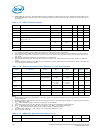
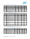
Notes:
1. For specific routing guidelines, see the appropriate Platform Design Guide (PDG) for details.
2. See the appropriate Platform Design Guide (PDG) for details.
3. IVT_ID_N land is a no connect on die.
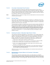
7.8.3.1 PCI Express* DC Specifications
The processor DC specifications for the PCI Express* are available in the PCI Express
Base Specification - Revision 3.0. This document will provide only the processor
exceptions to the
PCI Express Base Specification - Revision 3.0.
7.8.3.2 DMI2/PCI Express* DC Specifications
The processor DC specifications for the DMI2/PCI Express* are available in the PCI
Express Base Specification 2.0 and 1.0
. This document will provide only the processor
exceptions to the
PCI Express Base Specification 2.0 and 1.0.
7.8.3.3 Intel QuickPath Interconnect DC Specifications
Intel QuickPath Interconnect specifications are defined at the processor lands. Please
refer to the appropriate platform design guidelines for specific implementation details.
In most cases, termination resistors are not required as these are integrated into the
processor silicon.
7.8.3.4 Reset and Miscellaneous Signal DC Specifications
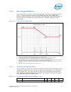
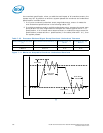
For a power-on Reset, RESET_N must stay active for at least 3.5 millisecond after V
CC
and BCLK{0/1} have reached their proper specifications. RESET_N must not be kept
asserted for more than 100 ms while PWRGOOD is asserted. RESET_N must be held
asserted for at least 3.5 millisecond before it is deasserted again. RESET_N must be
held asserted before PWRGOOD is asserted. This signal does not have on-die
termination and must be terminated on the system board.
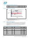
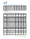
Table 7-23. Miscellaneous Signals DC Specifications
Symbol Parameter Min Typical Max Units Notes
IVT_ID_N Signal
V
O_ABS_MAX
Output Absolute Max Voltage 1.10 1.80 V 1
I
O
Output Current 0 μA1, 3
SKTOCC_N Signal
V
O_ABS_MAX
Output Absolute Max Voltage 3.30 3.50 V 1
I
OMAX
Output Max Current 1 mA 2


