


Vig390s Motherboard Manual V1.0
35
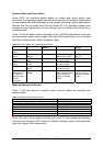
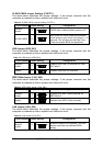
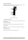
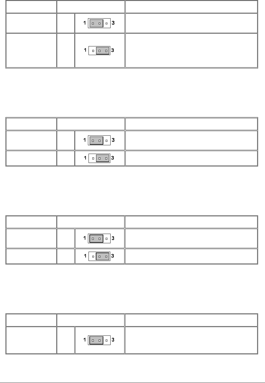
CLEAR CMOS Jumper Settings (CLRTC1)
The table below describes the jumper settings; if the jumper removed and the
computer is powered-up then a system boot failure will occur.
Table 12: CLEAR CMOS Jumper Settings (CLRTC1)
Function/Mode Jumper Setting Configuration
(Default)
Normal
1-2
CMOS data is retained when system is off
CLEAR CMOS 2-3
With power off, mains power disconnected
move jumper to pins 2 and 3 for about 5 ~ 10
seconds. This will also rest the Real Time
Clock and system BIOS set passwords.
USB Jumper (USB_EN1)
The table below describes the jumper settings; if the jumper removed and the
computer is powered-up then a system boot failure will occur.
Table 13: USB Jumper (USB_EN1)
Function/Mode Jumper Setting Configuration
(Default)
Enable
1-2
Enables front USB 2.0 controller for USB
6/6/7 and 8.
Disable 2-3
Disables front USB 2.0 controller.
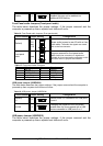
IEEE1394a Jumper (1394_EN1)
The table below describes the jumper settings; if the jumper removed and the
computer is powered-up then a system boot failure will occur.
Table 14: IEEE1394a Jumper (1394_EN1)
Function/Mode Jumper Setting Configuration
(Default)
Enable
1-2
Enables front IEEE-1394a controller for
IEEE1394a 2.
Disable 2-3
Disables front IEEE-1394a controller.
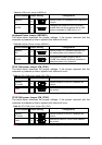
LAN Jumper (LAN_EN1)
The table below describes the jumper settings; if the jumper removed and the
computer is powered-up then a system boot failure will occur.
Table 15: LAN Jumper (LAN_EN1)
Function/Mode Jumper Setting Configuration
(Default)
Enable
1-2
Enables onboard LAN controller., this may
also be controlled via additional BIOS
setting.