


■ STATUS LED on page 21
■ ALARM LED on page 21
■ HA LED on page 22
■ RESET CONFIG Button on page 22
■ Built-In Gigabit Ethernet Ports on page 23
■ Console Port on page 23
■ AUX Port on page 23
■ USB Port on page 24
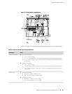
Physical Interface Modules (PIMs)
Physical Interface Modules (PIMs) provide the physical connection to various network
media types. For information about individual PIMs, see “Field-Replaceable
PIMs” on page 46.
For pinouts of PIM cable connectors, see “Network Cable Specifications and Connector
Pinouts” on page 223. For PIM replacement instructions, see “Replacing a
PIM” on page 172.
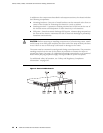
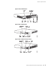
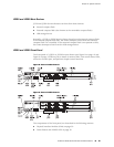
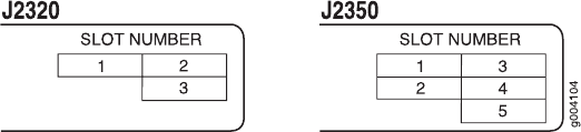
The J2320 front panel has three slots and the J2350 front panel has five slots for
field-replaceable PIMs. These slots are numbered from top to bottom and from left
to right as shown in Figure 10 on page 20.
Slot 0 is a fixed interface module that contains four built-in Gigabit Ethernet ports.
For more information, see “Built-In Gigabit Ethernet Ports” on page 23.
Figure 10: Slot Number Diagram on J2320 and J2350
Power Button and POWER LED
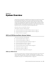
The power button is located on the left side of the front panel (see
Figure 1 on page 14). You can use the power button to power the Services Router
on and off. When you power on the router, the Routing Engine boots as the power
supply completes its startup sequence.
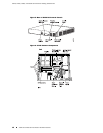
The POWER LED is located to the upper left of the LED dashboard. Table 7 on page
21 describes the POWER LED.
20 ■ J2320 and J2350 Services Router Hardware Features
J2320, J2350, J4350, and J6350 Services Router Getting Started Guide