


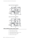
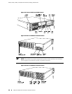
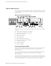
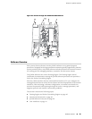
J4350 and J6350 Front Panel
The front panel of the Services Router (see Figure 19 on page 32) allows you to install
or remove PIMs, view router status LEDs, access the console port, and perform simple
control functions.
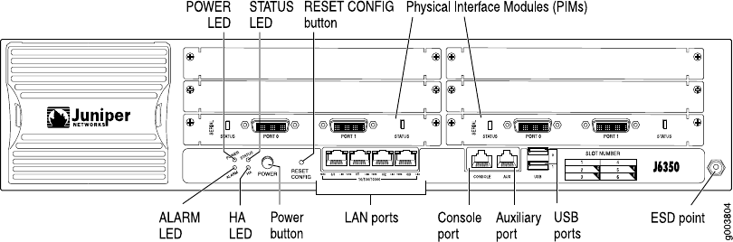
Figure 19: Front of J4350 and J6350 Chassis
The components of the front panel, from left to right, are described in the following
sections:
■ Physical Interface Modules (PIMs) on page 32
■ Power Button and POWER LED on page 33
■ STATUS LED on page 33
■ ALARM LED on page 34
■ HA LED on page 34
■ RESET CONFIG Button on page 35
■ Built-In Gigabit Ethernet Ports on page 35
■ Console Port on page 36
■ AUX Port on page 36
■ USB Port on page 36
Physical Interface Modules (PIMs)
Physical Interface Modules (PIMs) provide the physical connection to various network
media types. For information about individual PIMs, see “Field-Replaceable
PIMs” on page 46.
For pinouts of PIM cable connectors, see “Network Cable Specifications and Connector
Pinouts” on page 223. For PIM replacement instructions, see “Replacing a
PIM” on page 172.
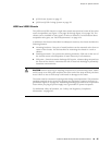
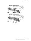
Each J4350 and J6350 Services Router has six front panel slots for field-replaceable
PIMs. These slots are numbered from top to bottom and from left to right as shown
in the slot number diagram on the front panel, shown in Figure 20 on page 33.
32 ■ J4350 and J6350 Services Router Hardware Features
J2320, J2350, J4350, and J6350 Services Router Getting Started Guide