


10
Names and Operations of Parts (Continued)
M
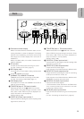
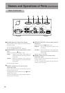
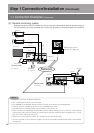
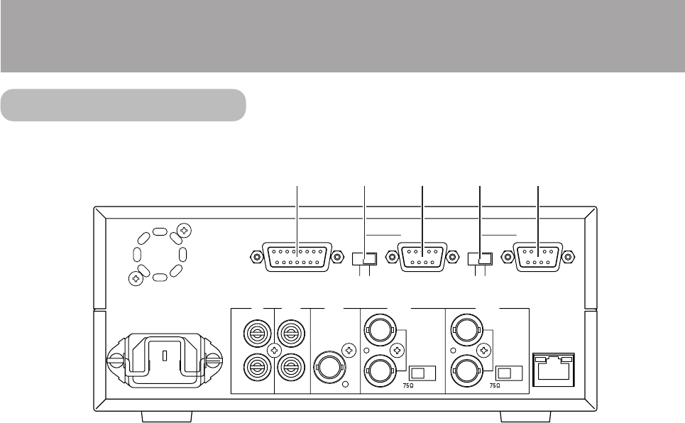
[ALARM] Alarm port (Dsub 15-pin, female)
Input terminals for alarm signals, and output terminals
for device control.
(
੬ See “Alarm Port”, page 18)
(੬ See “ALARM SETUP screen”, page 37)
N
[RS485/RS232C] Protocol select switch of Serial
Port 1
Selects the protocol of
O
SERIAL 1 port.
RS485: Performs input/output using signals with
electrical properties that comply with EIA/
ITA RS-485.
RS232C: Performs input/output using signals with
electrical properties that comply with EIA/
ITA RS-232C.
(Factory setting: RS232C)
O
[SERIAL 1] Serial Port 1 for device control
(Dsub 9-pin, male)
Used to connect to an external control device such as
a remote control unit, etc.
The signal protocol can be selected using the
N
RS485/
RS232C select switch.
The unit is equipped with a pass-through feature for
remote control via network.
P
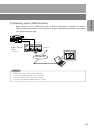
[SERVICE/CONTROL] Protocol select switch of
Serial Port 2
Selects the protocol of
Q
SERIAL 2 port.
SERVICE: Only used during servicing. Do not use
this setting.
CONTROL: Performs input/output using signals with
electrical properties that comply with EIA/
ITA RS-232C.
(Factory setting: CONTROL)
Q
[SERIAL 2] Serial Port 2 for device control
(Dsub 9-pin, male)
Used to connect to an external control device such as
a remote control unit, etc.
The unit is equipped with a pass-through feature for
remote control via network.
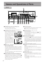
Back (Continued)
IN 2
100BASE-TX
OPEN
VIDEO
LOOP
THRU
SERIAL 1
SERVICE
CONTROL
SERIAL 2
OUT
VIDEO
IN 1
OPEN
LOOP
THRU
VIDEO
RESERVED
AC IN
R
L
OUT
AUDIO
ALARM
RS485
RS232C
IN
@7@6@5@4@3