


18
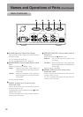
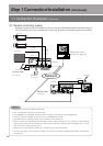
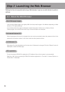
1-4 SERIAL Ports and ALARM Port
Signal names of SERIAL ports and ALARM port located on the back of the unit are shown
below.
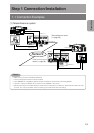
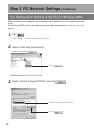
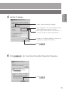
Step 1
Connection/Installation (Continued)
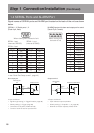
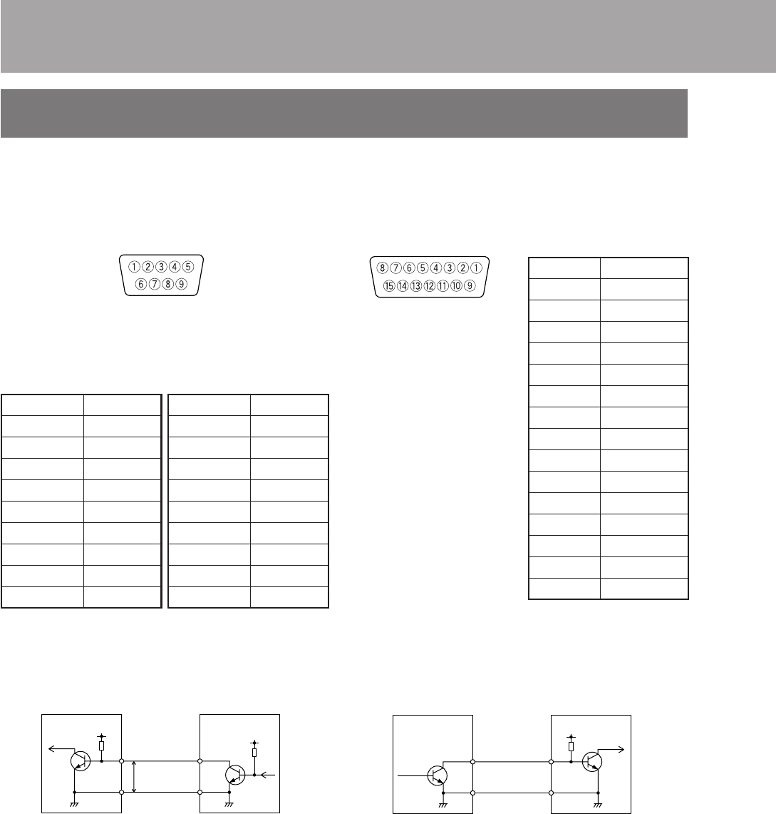
[SERIAL 1, 2] Serial ports 1, 2
(Dsub 9-pin, male)
When viewing from the back of unit
SERIAL 1 port
(when set to RS232C)
SERIAL 2 port
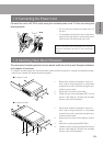
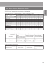
[ALARM] input port for alarm and output port for control
(Dsub 15-pin, female)
Pin no.
Signal name
1NC
2 RXD
3 TXD
4NC
5 GND
6NC
7NC
8NC
9NC
SERIAL 1 port
(when set to RS485)
Pin no.
Signal name
1NC
2 RX –
3 TX –
4NC
5 GND
6NC
7 TX +
8 RX +
9NC
For detailed setup concerning the SERIAL ports,
੬ see “Serial Port Setup screen”, page 40)
When viewing from
the back of unit
Pin no.
Signal name
1 OUTPUT 1
2 OUTPUT 2
3 OUTPUT 3
4 OUTPUT 4
5 OUTPUT 5
6 OUTPUT 6
7 OUTPUT 7
8 OUTPUT 8
9 INPUT 1
10 INPUT 2
11 INPUT 3
12 INPUT 4
13 GND
14 GND
15 GND
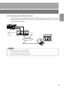
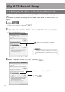
Alarm input port
<Input conditions>
• Signal length setting (੬ Trigger Duration, page 38)
• Polarity setting (੬ Trigger, page 38)
• Connection to 5V power, 10kΩ internally
• Current of 10mA or less for input terminal
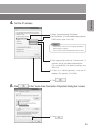
<Output conditions>
• Open collector output equivalent
• Polarity setting (੬ OutputPin 1 ~ 8, page 39)
• External connection capacity: DC5V, 10mA
Output terminal
Unit
Alarm input port
Example of sensor
INPUT
1~4
OUT
R
DC5V
Alarm input equivalent circuit
GND GND
R
VCC
5V
Unit
Output terminal
Example of controlled device
OUTPUT
1~8
IN
R
DC5V
GND GND