


9
Introduction
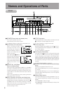
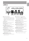
Back
G
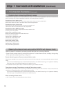
[75Ω/OPEN] Input 1, 75Ω terminal switch
75Ω terminal switch for the
H
VIDEO IN 1 terminal.
Select “OPEN” during loop-through connection. Other-
wise, select “75Ω”. Video may not be displayed cor-
rectly if the switch is not set properly.
(Factory setting: 75Ω)
H
[VIDEO IN 1] Video input terminal 1
Input terminal 1 for video signal. Used for inputting video
signal from a camera, etc.
I
[VIDEO OUT] Video output terminal
Output terminal for video signal.
Used only when in the Teleconference or Monitor mode.
J
[AUDIO OUT] Audio output terminal
Output terminal for audio signal. Used for connecting
audio input terminal of a monitor, etc.
Used only when in the Teleconference or Monitor mode.
(RESERVED: Currently cannot be used)
K
[AUDIO IN L/R] Audio input terminal
Input terminal for audio signals.
L and R channels can be used when in the ISMA mode.
The L channel terminal can be used when in the tele-
conference or Monitor mode.
L
[AC IN] AC power input terminal
Input commercial AC120V using the included power
cord.
(੬ See “Connecting the Power Cord”, page 19)
IN 2
100BASE-TX
OPEN
VIDEO
LOOP
THRU
SERIAL 1
SERVICE
CONTROL
SERIAL 2
OUT
VIDEO
IN 1
OPEN
LOOP
THRU
VIDEO
RESERVED
AC IN
R
L
OUT
AUDIO
ALARM
RS485
RS232C
IN
@2
@1 @0 !9 !8 !7
!6
!5
!4
!3
!2
0
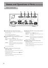
Connection number display
While in the Teleconference or Monitor mode, the con-
necting destination number is displayed. The display
will flash when establishing connection and the lamp
will change to a constant display when connection is
established.
While in the ISMA mode, the number of streams trans-
mitted is displayed.
A
CF card slot
CF card can be inserted after removing the screw.
(੬ See “Inserting a CF Card”, page 17)
B
RXD display lamp
The lamp turns on when data is being sent/received
via the
C
100BASE-TX terminal.
C
[100BASE-TX] 100BASE-TX terminal
100BASE-TX terminal for connecting a LAN cable.
(੬ See “Connecting a LAN Cable, page 17)
D
LINK display lamp
The lamp turns on when the 100BASE-TX terminal is
ready for communication.
E
[75Ω/OPEN] Input 2, 75Ω terminal switch
75Ω terminal switch for the
F
VIDEO IN 2 terminal.
Select “OPEN” during loop-through connection. Other-
wise, select “75Ω”. Video may not be displayed cor-
rectly if the switch is not set properly.
(Factory setting: 75Ω)
F
[VIDEO IN 2] Video input terminal 2
Input terminal 2 for video signal. Used for inputting video
signal from a camera, etc.