


16
HOW TO USE “MAIN MENU” (cont'd)
AREA MARKER:
Controls ON/OFF and other settings of the MARKER,
SAFETY MARKER, and ZOOM functions included in
the AREA MARKER function.
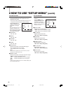
Press the button to
display the setting menu
illustrated on the right.
NOTES:
• For the 4:3 screen ratio, only
SAFETY MARKER and R-SAFETY MARKER are displayed.
• To set up non-“R-” items, press the AREA MARKER button on the
front panel. An external control system should not be operated at
this time.
• To set up “R-” items, set the AREA MARKER function to ON via
external control.
• Use the MAKE/TRIGGER terminal for external control of AREA
MARKER function. Please note that this will only work when the
AREA MARKER button on the front panel has been pressed (the
AREA MARKER lamp will be illuminated). For details, refer to
“HOW TO USE THE MAKE/TRIGGER TERMINAL” on page 23.
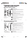
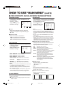
Ⅵ MARKER SELECT/R-MARKER SELECT
It displays the area of the aspect ratio that has been
set in the ASPECT SELECT/R-ASPECT SELECT,
superimposed on the current screen.
OFF : MARKER does not function.
LINE :Displays the area with an outline.
S.HALF : The area outside the specified screen ratio is
displayed as a 50% transparency.
HALF+L: The area of the specified screen ratio is indicated
by an outline, and the area outside of that is
displayed as a 50% transparency.
S. BLK : The area outside the specified screen ratio is
black. Only the portion of the picture within the
designated area is displayed.
BLK.+L : The area of the specified screen ratio is indicated
by an outline, and the area outside of that
becomes black so that only the area inside the
line is displayed.
Ⅵ ZOOM/R-ZOOM
Zooms the center of the marked area.
OFF: Does not zoom.
ON : Zooms.
NOTES:
• Does not function when under-scan is operated.
• To adjust the zoom picture size, refer to “ZOOM V. SIZE” and “
ZOOM H. SIZE” on page 21.
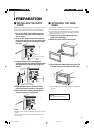
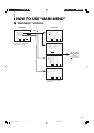
Ⅵ ASPECT SELECT/R-ASPECT SELECT
Selects the screen aspect ratio.
• 4:3/13:9/14:9
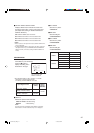
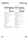
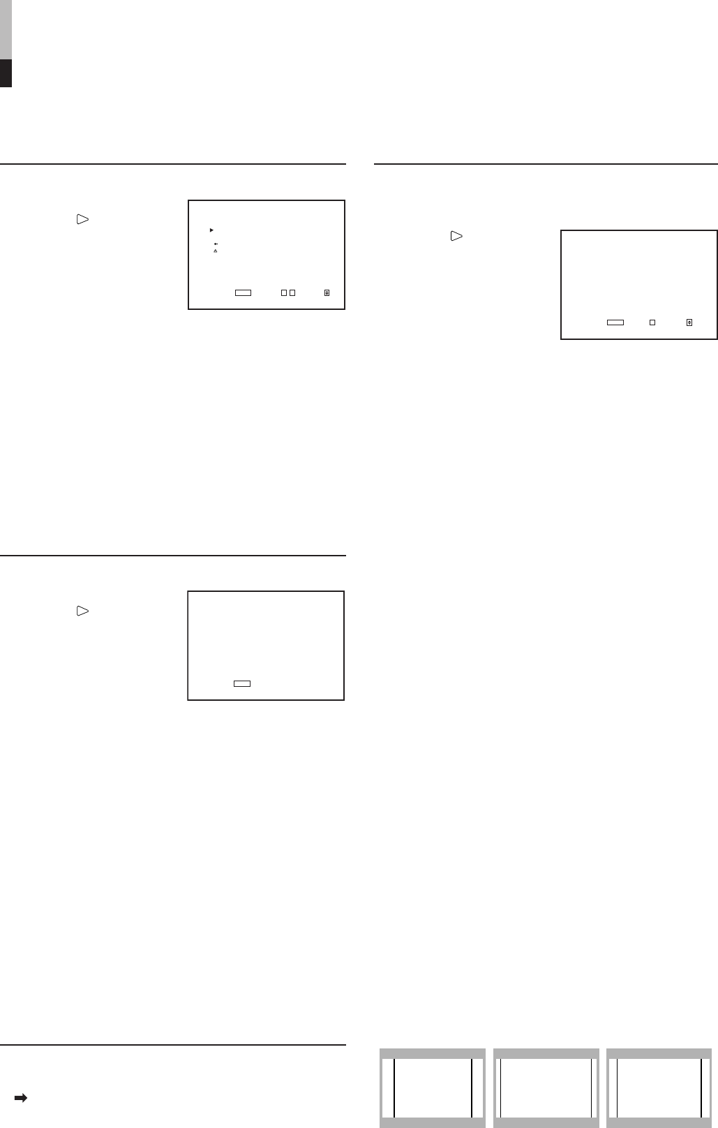
<AREA MARKER>
MARKER SELECT :LINE
ZOOM :ON
ASPECT SELECT : 4:3
SAFETY AREA :85
R-MARKER SELECT :LINE
R-ZOOM :OFF
R-ASPECT SELECT : 13:9
R-SAFETY AREA :85
EXIT:
MENU
ENTER:+ SELECT:
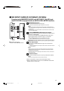
APERTURE CONTROL
Compensates the frequency characteristics of the
input video signal.
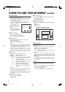
Press the
button to
display the setting menu
illustrated on the right.
Ⅵ LEVEL
Adjusts the compensate value. The higher the
number is, the larger the compensate value gets.
• 00 ~ +10
Ⅵ CONTROL FREQ.
Adjusts the frequency compensation.
HIGH: Compensates the high frequencies.
LOW : Compensates the low frequencies.
OFF : Deactivates the aperture compensation.
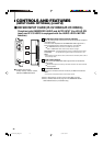
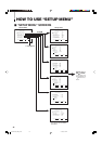
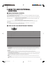
<SLOT CONDITION>
INPUT A : VIDEO-1
INPUT B : VIDEO-2
INPUT C : COMPO.
INPUT D : RGB
INPUT E : NO SLOT
INPUT F : NO SLOT
EXIT:
MENU
Ⅵ ITEM CONTENTS AND ADJUSTMENT RANGE/SETTINGS
<APERTURE CONTROL>
LEVEL : 00
CONTROL FREQ. :HIGH
sub menu
reset
EXIT:
MENU ADJUST:- + SELECT:
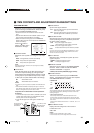
INPUT A/INPUT B : Status of SLOT1
INPUT C/INPUT D : Status of SLOT2
INPUT E/INPUT F : Status of SLOT3
VIDEO-1/VIDEO-2 : With VIDEO input card is installed.
COMP./RGB :With Component/RGB input card is
installed.
SDI1/SDI2 : With SDI input card is installed.
HD SDI1/HD SDI2 : With HD SDI input card is installed.
NOTES:
• If an input card is compatible with EMBEDDED AUDIO, an asterisk
(*) is displayed its name. (Example: HD SDI*)
• If an input card is compatible with both EMBEDDED AUDIO and
AUDO LEVEL METER, two asterisks (**) are displayed after its
name. (Example: HD SDI**)
• The “--” indication may appear. This means that no signal is input
to the corresponding INPUT, either because no input card is
installed or because the input card only has a single input line.
sub menu POSITION
Selects the display position of the sub menu superim-
posed on the screen.
For details, refer to “To change the position of the sub-menu
display” on page 14.
SLOT CONDITION
Displays the status of the input cards installed in each
of the input card slots.
Press the button to
display the setting menu
illustrated on the right.
4:3 14:9 13:9
LCT1424-001A_EN_p2-17 4/22/03, 11:12 AM16