


7
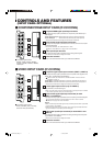
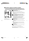
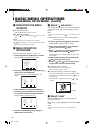
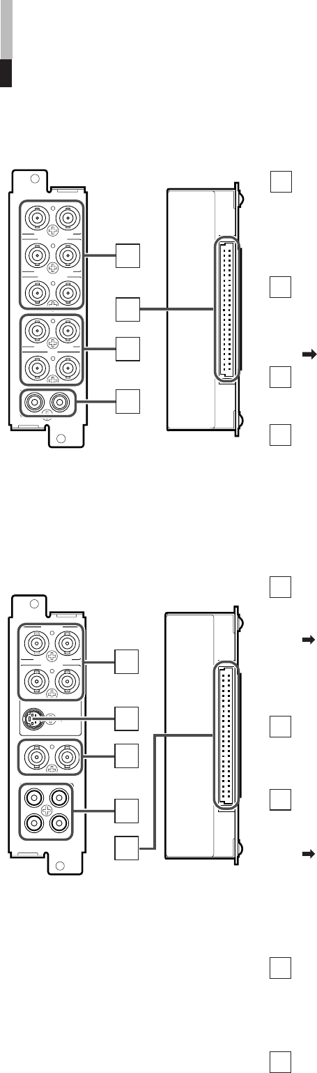
Component/RGB signal input/output terminals
Input (IN) and output (OUT) terminals for component (color difference) or
RGB signals.
Select component signal: INPUT SELECT A (SLOT1)/C (SLOT2)/E (SLOT3)
Select RGB signal : INPUT SELECT B (SLOT1)/D (SLOT2)/F (SLOT3)
* The IN and OUT terminals are bridge-connected (auto termination).
Synchronized signal input/output terminals
Input (IN) and output (OUT) terminals for the vertical, horizontal or complex
synchronized signals.
• To use these terminals, set “SYNC SELECT” to “EXT”.
Refer to “SYNC SELECT” on page 19 for more information.
Audio input/output terminals
Input (IN) and output (OUT) terminals for the analog audio signals.
• The IN and OUT terminals are bridge-connected.
Connection terminal
Attach to the connection terminal of your Multi-Format Monitor.
1
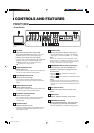
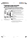
CONTROLS AND FEATURES
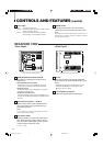
(INPUT CARD: OPTIONAL)
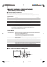
Ⅵ COMPONENT/RGB INPUT CARD (IF-C01COMG)
Ⅵ Compatible signal formats:
NTSC (3.58 MHz), PAL (4.43 MHz),
black-and-white (50 Hz/60 Hz)
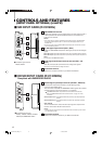
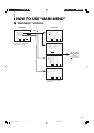
Ⅵ VIDEO INPUT CARD (IF-C01PNG)
Ⅵ Compatible signal formats:
480/60i, 576/50i, 576/50p, 480/60p,
720/60p, 1035/60i, 1080/50i, 1080/60i,
1080/24psF
Composite signal input/output terminals (VIDEO 1, VIDEO 2)
Input (IN) and output (OUT) terminals for the composite video signals of the
NTSC, PAL, and black/white (50 Hz/60 Hz).
NTSC and PAL are switched in the “COLOR SYSTEM”. Refer to “COLOR
SYSTEM” on page 19.
Select VIDEO 1: press INPUT SELECT A (SLOT1)/C (SLOT2)/E (SLOT3) buttons.
Select VIDEO 2: press INPUT SELECT B (SLOT1)/D (SLOT2)/F (SLOT3) buttons.
* The IN and OUT terminals are bridge-connected (auto termination).
S-video signal input terminal (only for VIDEO 2)
Input terminal for the S-video signal.
• When an S-video signal is input to this terminal and a video signal is input to VIDEO
2, the S-video signal has priority over the video signal.
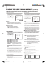
Synchronized signal input/output terminals (for both
VIDEO 1 and VIDEO 2)
Input (IN) and output (OUT) terminals for the complex synchronized signals.
To use these terminals, set “SYNC SELECT” to “EXT”. Refer to “SYNC
SELECT” on page 19 for more information.
NOTES:
• When an external synchronized signal is input, external synchronization is prioritized
for both VIDEO 1 and VIDEO 2.
• External synchronization does not function when a video signal (except black burst
signal) is included in the complex synchronized signal.
Audio signal input/output terminals (for both VIDEO 1 and
VIDEO 2)
Input (IN) and output (OUT) terminals for analog audio signals correspond-
ing to VIDEO 1 and VIDEO 2.
• The IN and OUT terminals are bridge-connected.
Connection terminal
Attach to the connection terminal of your Multi-Format Monitor.
1
2
3
4
2
3
4
5
B/P
B
/B-Y
G/Y
OUTIN
OUTIN
R/P
R
/B-Y
OUTIN
VD
OUTIN
HD/C
S
OUTIN
OUTIN
AUDIO
OUT
IN
1
2
3
4
VIDEO 1
OUT
IN
AUDIO 2
AUDIO 1
OUT
IN
VIDEO 2
OUT
Y/C IN
IN
OUT
IN
EXT.SYNC
1
2
3
4
5
LCT1424-001A_EN_p2-17 11/4/03, 5:08 PM7