


31
SPECIFICATIONS
(Input card : optional)
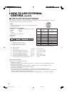
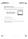
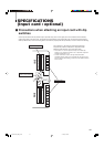
Ⅵ Precautions when attaching an input card with dip
switches
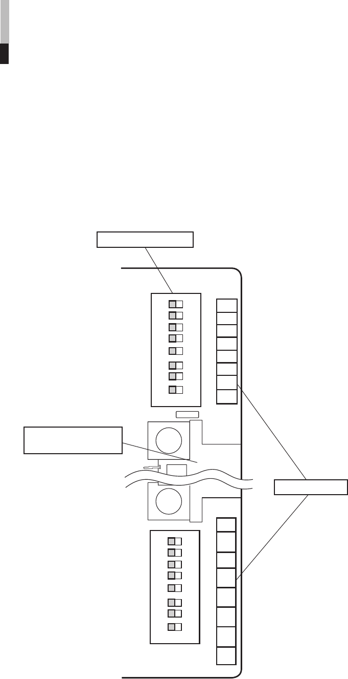
Some input cards have two dip switch arrays: dip switch array S101 on the upper part of the connector terminal and dip
switch array S102 on the lower part. The surface of these switches is pre-coated with a film on shipment from the factory.
When problems arise, such as not being able to set functions properly with the dip switches, be sure to check the following:
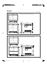
The numbers 1 to 16 on the PC board to the right of the
respective dip switches indicate the respective switch.
Make sure that switches 1 and 16 are set to OFF.
• The numbers 1 to 8 on the dip switch array S101 indicate dip
switches 1 to 8, while the numbers 1 to 8 on dip switch array S102
indicate dip switches 9 to 16.
• A switch is ON when it is set to the right side (where ON is
indicated) and OFF when it is set to the left side. The figure on the
left is the factory default setting, wherein all of the selector switches
are set to OFF.
2
3
4
5
6
7
8
1
O
N
12345678
2
3
4
5
6
7
8
1
O
N
S101
S102
9
10
111213141516
Dip switch array S101
Connector terminal
(side for slot insertion)
Switch numbers
LCT1424-001A_EN_p18-32 11/4/03, 5:13 PM31