


24
Ⅵ HOW TO USE THE RS-485 TERMINAL
You can control the monitor from the controller (exclusive for this monitor) or your PC via the RS-485 terminal. For details on
operating the monitor from the PC, consult the service centre.
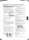
1. Cable
Prepare a straight cable with a D-sub connector (9-pin, male) and a D-sub
connector (9-pin, male)
2. Communications Specifications
Baud Rate : 4800/9600/19200 (factory pre-set; 4800)
Data Bits : 8 bits
Parity : No parity
Stop Bits : 1
Communication Cord : ASCII Cord
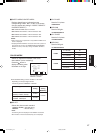
3. Commands
Format
Header ID Command ID Command Content Data CR
Header
! Control from the PC to the monitor
? Reference from the PC to the monitor
@ Answer from the monitor to the PC
ID + Command + Data
B Basic command Characters 00, 01 or No data
D Command for adjusting the picture size 00 ~ 08 U, D (U: UP, D: DOWN)
S Command for adjusting the picture quality 00 ~ 05 U, D (U: UP, D: DOWN)
M Command for selecting the menu item 00 ~ 0E 00, 01, 10, 11
F Command for selecting the menu item 00 ~ 10 00, 01, 02, 03, 04, 05
W Command for adjusting the white balance 00 ~ 05 U, D (U: UP, D: DOWN)
C Command for inquiring for the monitor’s status 00 0 ~ 655
Communication Procedures
The following is the communication procedures.
1. Starting the communication
Receives the connection command (!XXBCN1Cr) from the PC [ Sends the monitor’s status (@XXBOKCr) to the PC
2. Performing the external control
Receives the control command (!XXXXCr) from the PC [ Sends the monitor’s status (@XXBOKCr) to the PC
* The monitor repeats these receiving and sending if necessary.
3. Terminating the communication
Receives the termination command (!XXBCN0Cr) [ Sends the monitor’s status (@XXBOKCr) to the PC
* Hand-shake communication is used. This means that after sending a command to the monitor, the PC must receive a status
return from the monitor before sending the next command.
* When the monitor is controlled by a PC via RS-485, a conversion adapter (RS-232Cp[RS-485) is also required.
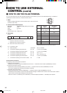
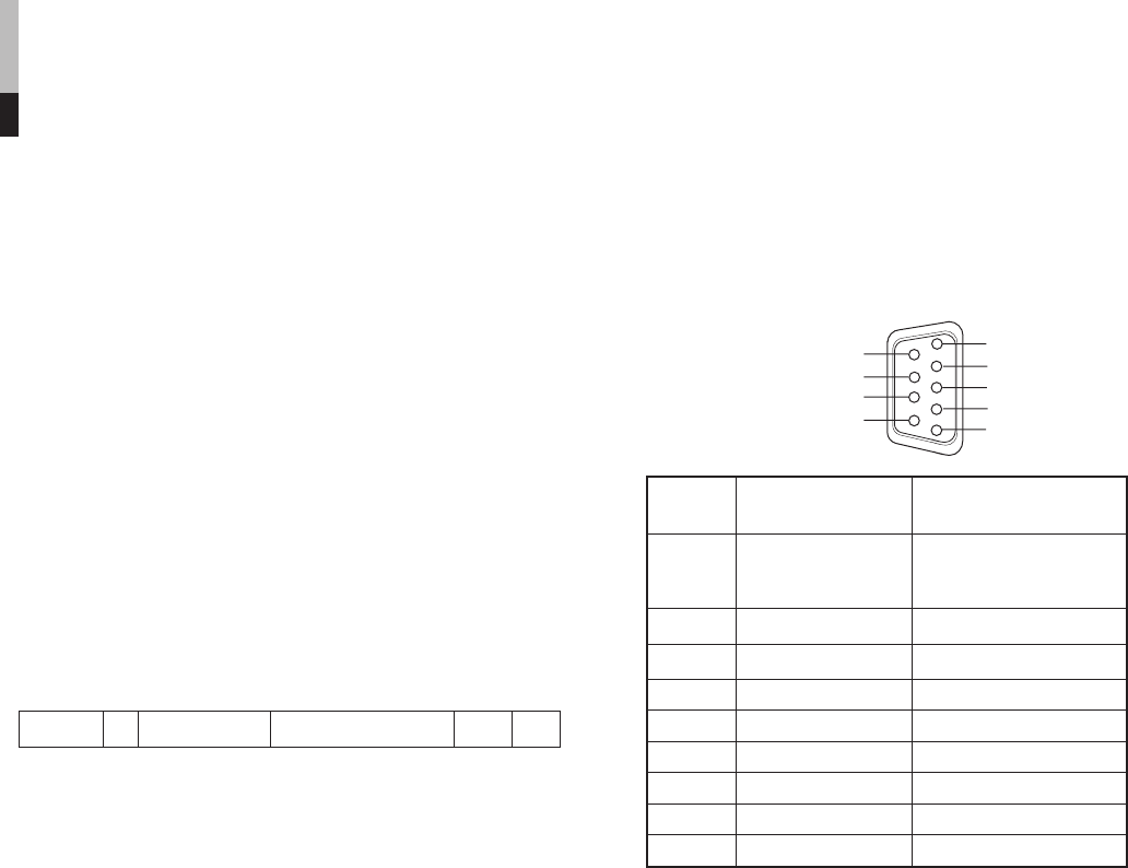
4
3
2
1
9
8
5
7
6
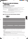
Pin No. IN terminal OUT terminal
signal signal
1 5V Power (for
controller exclusively NC
for this monitor)
2TD+ TD+
3RD+ RD+
4NC NC
5NC NC
6NC NC
7TD– TD–
8RD– RD–
9NC NC
* The 5V power supply of the 1st terminal is for the controller
exclusively for this monitor. Do not use it for other devices.
HOW TO USE EXTERNAL
CONTROL
(cont'd)
LCT1423-001A_p18-32 4/29/03, 5:08 PM24