


19
ENGLISH
Ⅵ ITEM CONTENTS AND ADJUSTMENT RANGE/SETTINGS
FUNCTION SETTING
Selects the control systems for the COLOR SYSTEM,
synchronized signal, RUSH DELAY TIME, tally lamp
colours, and MAKE/TRIGGER terminal.
• Checks the amount of time that the monitor has been
used.
• Sets the AUTO INPUT function ON/OFF. (When an input
card compliant with AUTO INPUT is installed.)
• Selects the audio channel group for the EMBEDDED
AUDIO. (When an input card compliant with EMBEDDED
AUDIO is installed.)
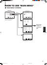
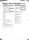
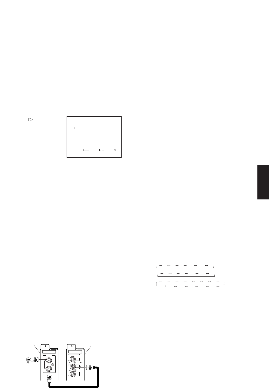
Press the button to
display the setting menu
illustrated on the right.
Ⅵ COLOR SYSTEM
Selects the colour system when using the video input
card.
AUTO : Changes NTSC and PAL automatically.
NTSC : Keeps the colour system NTSC.
PAL : Keeps the colour system PAL.
NOTE:
Normally select AUTO. However, if the input signal is unstable,
select NTSC or PAL.
Ⅵ AUTO INPUT
When HD SDI signal and D1 SDI signal need to be
switched to input accordingly by one signal cable,
AUTO INPUT automatically detects whether a signal
is being input to Input A (HD SDI input card) or Input
C (SDI input card) and switches INPUT accordingly.
ON : AUTO INPUT is ON.
OFF : AUTO INPUT does not function.
NOTES:
• Functions only when input card compatible with AUTO INPUT is
used.
• “INPUT SELECT ERROR” is displayed for approx. 3 seconds
when different signal cables are connected to each INPUT A and
INPUT C and signals are input to the each of them.
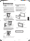
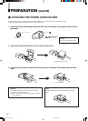
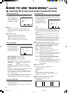
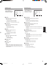
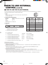
Preparation for the AUTO INPUT function (See below
illustration)
1. Insert HD SDI input card to SLOT1, and SDI input card to
SLOT2 (both cards need to be compatible with AUTO
INPUT), then connect the signal cable.
2. Input HD SDI signal or D1 SDI signal to HD SDI input
card.
Ⅵ SYNC SELECT
Synchronized signal selection.
INT. : The input video signal is synchronized with the
built-in sync signal.
EXT. : The input video signal is synchronized with an
external signal from an external sync terminal.
Ⅵ RUSH DELAY TIME
Sets the time when the power supply to the monitor’s
circuits (excluding the micro computers) starts after
the power switch is pressed.
STD. : The power supply starts approx.
1 second after the power switch is pressed.
SLOW : The power supply starts approx.
3.2 seconds after the power switch is pressed.
NOTE:
If you are going to turn several Multi-Format Monitors on at the
same time, it is recommended to apply SLOW to some of the
monitors to control rush current.
Ⅵ TALLY SELECT
Selects the colour of the tally lamp (when lit) on the
upper front panel.
GREEN : The tally lamp lights in green.
RED : The tally lamp lights in red.
Ⅵ REMOTE SYSTEM
Selects the control system for the MAKE/TRIGGER
terminals. Refer to “HOW TO USE THE MAKE/
TRIGGER TERMINAL” on page 23.
• MAKE (make contact)/TRIGGER (trigger contact)
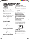
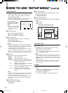
Ⅵ E.AUDIO GROUP
Selects the audio channel group for EMBEDDED
AUDIO. It is displayed when an input card compliant
with EMBEDDED AUDIO is installed.
• 1G/2G/1-2G
1G :
2G :
1-2G :
NOTE:
The auto setting mixes and outputs all 8 signal channels. Sets the
output level automatically by detecting the number of channels
receiving the signal.
* About sound output level
Sound output level is set to a standard output level for all
channels when several sound channels are output at the same
time. The more channels are selected, the lower each channel’s
level will be.
(Each channel's level becomes half for 1– 2 channel, 1/4 for 1– 4
channel.)
Ⅵ HOUR METER X100h
Displays the total usage time of the monitor in
hundred-hour units.
• 000 ~ 655
NOTES:
• When the timer passes 655, it returns to 000.
• The timer does not count the usage time under one hour.
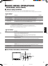
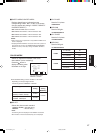
<FUNCTION SETTING>
COLOR SYSTEM :AUTO
AUTO INPUT :ON
SYNC SELECT :INT.
RUSH DELAY TIME :STD.
TALLY SELECT :GREEN
REMOTE SYSTEM :MAKE
E.AUDIO GROUP :1G
HOUR METER X100h :000
EXIT:
MENU
ADJUST:- + SELECT:
1ch 2ch 3ch 4ch 1-2ch 3-4ch 1-4ch
5ch 6ch 7ch 8ch 5-6ch 7-8ch 5-8ch
AUTO 5-8ch 1-4ch 7-8ch 5-6ch 3-4ch
1ch 2ch 3ch 4ch 5ch 6ch 7ch 8ch 1-2ch
IN
OUT
E.AUDIO
HD SDI 1
IN1
IN2
SWITCHED
OUT
E.AUDIO
SDI
SLOT2
SLOT1
D1 SDI input card
compatible with
AUTO INPUT
HD SDI input card
compatible with
AUTO INPUT
LCT1423-001A_p18-32 4/29/03, 5:08 PM19