


6
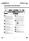
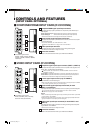
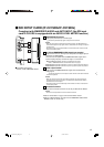
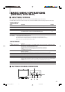
REAR/SIDE VIEW
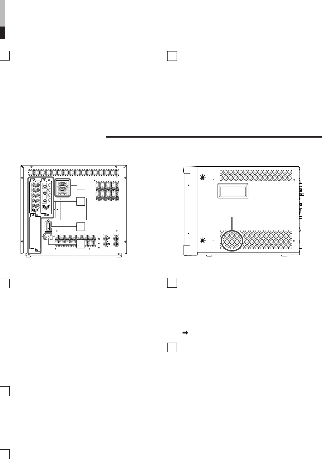
<Rear Panel>
REMOTE (external control) terminals
Terminals for controlling the monitor from an
external unit.
MAKE/TRIGGER terminal (Upper):
Enables the monitor to be controlled by closing the
circuit (point of contact) connected to the terminal.
RS-485 IN terminal:
Enables the monitor to be controlled from a personal
computer via a serial cable.
RS-485 OUT terminal (Lower):
Enables a cascade control connection. Multiple moni-
tors can be controlled by the device connected to the IN
terminal.
Input card slots (SLOT 1 – SLOT 3)
Optional input cards can be installed in these
slots. Input cards are not provided when you
purchase the monitor.
NOTE:
It is not possible to input video or audio signals to the monitor
when no input cards are installed.
Main power switch
Press the switch to turn the main power ON or
OFF. When the main power is ON, the power
lamp on the front panel lights in yellow and the
monitor enters the stand-by mode.
• I : ON ⅜ : OFF
G/Y
OUTIN
OUTIN
R/P
R
/B-Y
SLOT1SLOT3
SLOT2
MAIN POWER
OUTIN
VD
OUTIN
HD/C
S
OUTIN
OUTIN
AUDIO
OUT
IN
B/P
B
/B-Y
AUDIO
OUT
IN
SWITCHED
OUT
HD SDI 1
HD SDI 2
IN
IN
22
23
24
MAKE/TRIGGER
REMOTE
21
RS-485
IN
OUT
25
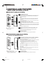
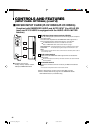
<Side Panel>
21
22
23
24
AC inlet
Power input connector. Connect the provided AC
power cord to an AC outlet (120 V/230 V AC, 50 Hz/
60 Hz).
* Attach the provided Power Cord Holder to prevent
accidental disconnection of the AC power cord.
Refer to page 12 for details.
Built-in speaker (monaural)
Outputs the selected INPUT audio signal.
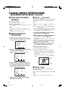
CONTROLS AND FEATURES (cont'd)
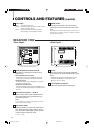
Power lamp
Unlit : The main power is OFF.
Orange : The main power is ON, but the monitor’s power
is OFF (in stand-by mode).
Green : The main power is ON, and the monitor’s
power is ON (in normal operation mode).
POWER switch
Press the power switch to turn the monitor’s
power ON or OFF when the main power is ON.
NOTE:
When RUSH DELAY TIME is set to SLOW in the set-up menu, it
takes approx. 3.2 seconds for the power to actually turn ON after
the power switch is pressed.
19 20
(Rear view of DT-V1910CG shown) (Side view of DT-V1910CG shown)
25
LCT1424-001A_EN_p2-17 4/18/03, 3:34 PM6