


23
HOW TO USE EXTERNAL
CONTROL
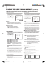
Ⅵ ABOUT EXTERNAL CONTROL
The Multi-Format Monitor has two external control terminals.
One is the MAKE/TRIGGER terminal, which allows the monitor to be controlled by the MAKE(make contact) or TRG. (trigger
contact) method selected in the function setting.
MAKE (make contact system): Controls functions either by short-circuiting (short with GND of 15th terminal) or stable disconnec-
tion (terminal open) of the controlled terminal.
TRG. (trigger system) : Controls the function by instantaneously (one second) short-circuiting (short with GND of 15th
terminal) the controlled terminal.
* MAKE or TRIGGER are selected from REMOTE SYSTEM in the setup menu.
The other terminal used for remote control is the RS-485 terminal, and this allows the monitor to be controlled by serial
communication.
NOTE: Control priority is in the following order; 1 MAKE/TRIGGER terminal > 2 RS-485 terminal > 3 front panel buttons.
When trigger contact is on, the front panel buttons can be operated.
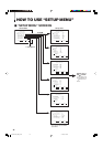
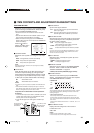
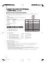
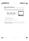
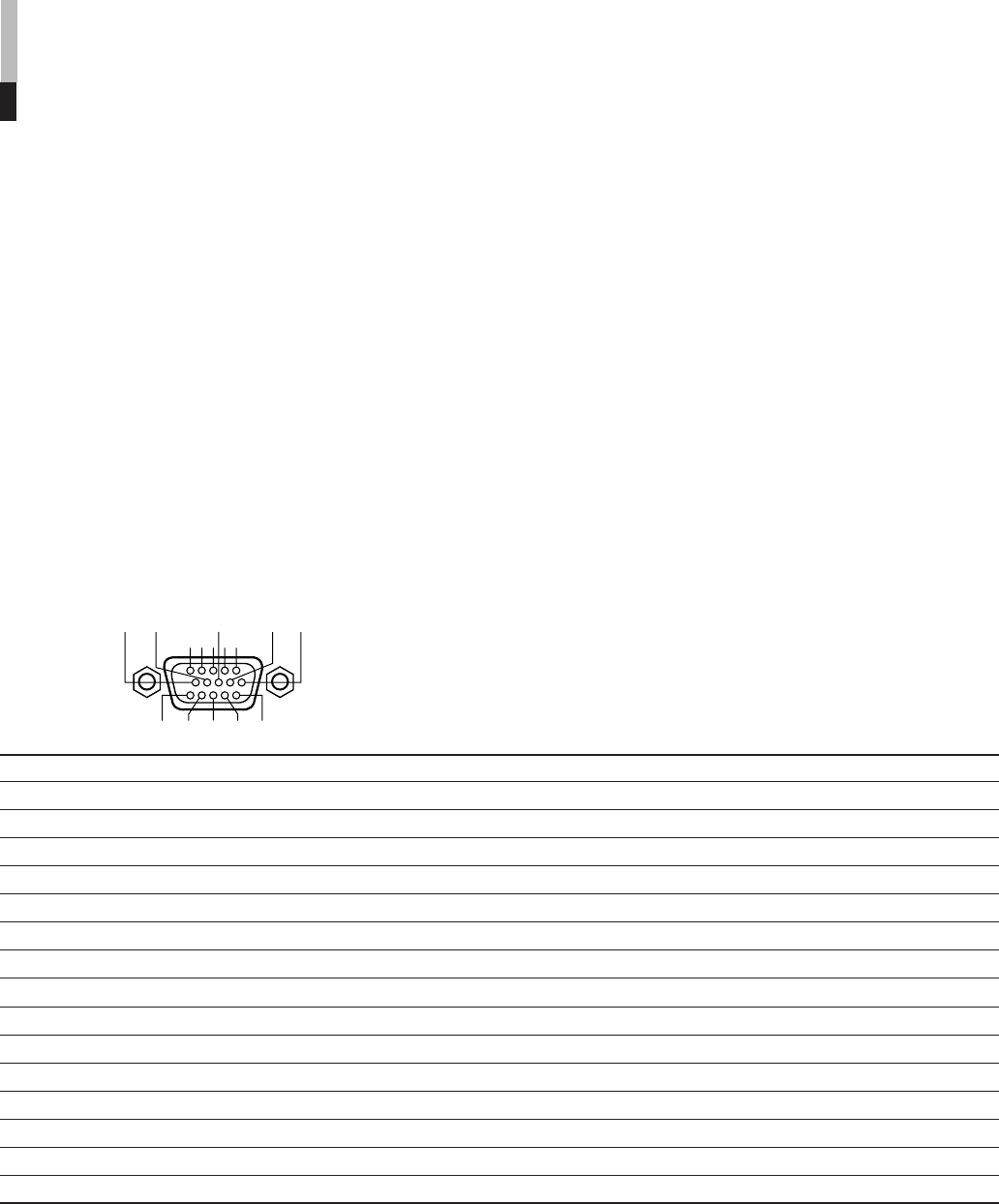
10 9 8
54321
7
6
1415 13 12 11
*1 : The TRIGGER (trigger contact) system switches each setting by instantaneously (approx. 1 second) short-circuiting (short with GND of 15th terminal) the
controlled terminal.
*2 : TALLY (1st terminal) and EXTERNAL CONTROL (14th terminal) must be controlled with the MAKE (make contact) system even under the TRIGGER (trigger
contact) system.
*3 : Activating each with “R-” or without “R-” setting in the AREA MARKER menu is possible. Refer to “AREA MARKER” on page 16 for details.
Operation
1. Short-circuit EXTERNAL CONTROL (14th terminal) to GND (15th terminal) to activate the external control.
2. Under the MAKE system, controls each function by short-circuiting (short with GND of 15th terminal) or stable disconnection
(terminal open) of the controlled terminal.
3. Under the TRIGGER (trigger contact) system, controls each function by Pulse Control, that is by instantaneously (approx. 1
second) short-circuiting (short with GND of 15th terminal) the controlled terminal.
NOTES:
• When using INPUT A (the 2nd pin) through INPUT F (7th terminal), only the terminal in use should be short-circuited, the others must be
disconnected.
• Under the TRIGGER system, multiple terminals cannot be short-circuited to GND (15th terminal). Be sure to short-circuit the single terminal to
GND.
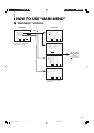
No. Functions to be controlled Disconnection Short-circuiting *1
1 Turns on the tally lamp Off On *2
2 Changes the input to INPUT A Invalid Valid
3 Changes the input to INPUT B Invalid Valid
4 Changes the input to INPUT C Invalid Valid
5 Changes the input to INPUT D Invalid Valid
6 Changes the input to INPUT E Invalid Valid
7 Changes the input to INPUT F Invalid Valid
8 COLOR OFF Off On
9 AREA MARKER Off On
10 ASPECT Off On
11 TALLY SELECT GREEN RED
12 AREA MARKER set-up without “R-” with “R-” *3
13 STATUS DISPLAY ON OFF
14 External Control Invalid Valid *2
15 GND
Ⅵ HOW TO USE THE MAKE/TRIGGER TERMINAL
LCT1424-001A_EN_p18-32 4/22/03, 11:14 AM23