


11
ENGLISH
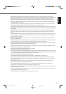
DISPLAY ASPECT POWER
RGB
COMPO.
VIDEO B
VOLUME
MULTIPLE
MODE ID SET
MONITORADJUSTMENT
VIDEO A
MUTING
MENU/EXIT
RM-C575 REMOTE CONTROL UNIT
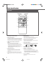
ID
RS232C CONTROL AC INPUT MAIN POWER
REMOTE CONTROL
WIRED
(MULTIPLE MONITOR ADJUSTMENT)
(100V)
SPEAKER OUT
RL
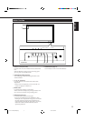
I
IN
OUT
INTERNAL EXTERNAL
AUDIO
PC
AUDIOVIDEOAUDIOVIDEOAUDIOVIDEO
VIDEO B COMPONENT
RGB
VIDEO A
Y
L/
MONO
L/
MONO
R
R
Y/CY/C
P
B
/
B-Y
P
R
/
R-Y
L/
MONO
R
IN
OUT
IN
OUT
L/
MONO
R
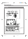
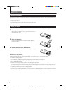
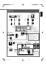
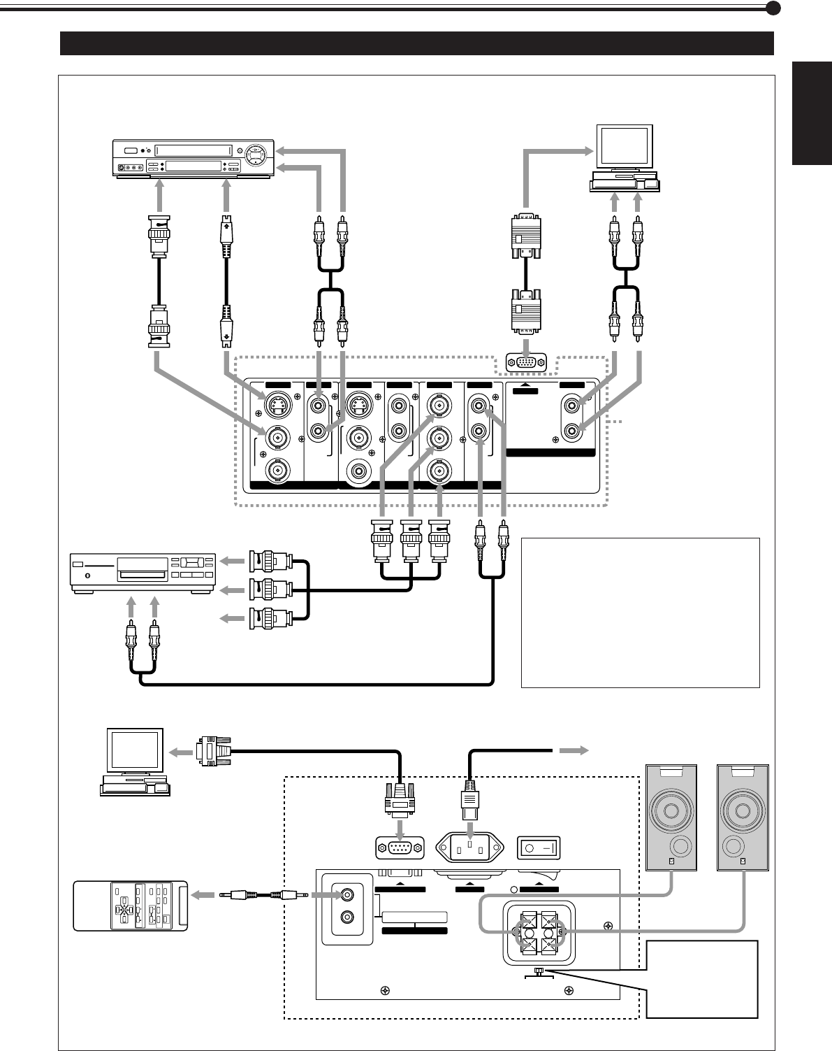
Connection Examples
Personal computer
(used as the playback source)
To audio
output
terminals
To RS-232C
terminal
Remote control
Personal computer
(used to control the Monitor)
Remote
control
cable
(supplied)
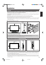
When using
external
speakers, set this
to EXTERNAL.
To speaker
input
terminals
Hi-vision equipment/
DVD, etc.
VCR
To audio output terminals
To video output
terminals
External
Speakers
Power cord ( supplied)
To a wall outlet
To audio output
terminals
To monitor
output
terminal
To S-video
output
terminal
To video
output
terminal
Connecting a VCR
• A VCR can also be connected to the
VIDEO B terminal.
• When both the video and S-video
terminals are connected, the S-video
terminal will have priority.
• The video output terminal of the
VIDEO B terminal can be used as the
video input terminal.
These terminals are not
available for
GD-V4200PCE and
GD-V4200PCE-G.
To use them, you need
to install video interface
kit (IF-C420P1W), which
is separately purchased.
04-11.GD-V4200PZW-A[EN]/f 00.2.23, 5:22 PM11