


2
INSTALLATION
ANTENNA CONNECTION
The type of the antenna system, consisting of the
antenna, ground, and feed line, will greatly affect the
successful performance of the transceiver. Use a
properly adjusted 50 Ω antenna of good quality to let
your transceiver perform at its best. Use a good-quality
50 Ω coaxial cable and a first-quality connector for the
connection. Match the impedance of the coaxial cable
and antenna so that the SWR is 1.5:1 or less. All
connections must be clean and tight.
While the transceiver’s protection circuit will activate if
the SWR is greater than 2.5:1, do not rely on protection
to compensate for a poorly functioning antenna system.
High SWR will cause the transmit output to drop, and
may lead to radio frequency interference to consumer
products such as stereo receivers and televisions. You
may even interfere with your own transceiver. Reports
that your signal is garbled or distorted, especially at
peak modulation, may indicate that your antenna
system is not efficiently radiating the transceiver’s
power. If you feel a tingle from the transceiver’s cabinet
or the microphone’s metal fittings when you modulate,
you can be certain that, at the least, your coax
connector is loose at the rear of the radio and, at the
worst, your antenna system is not efficiently radiating
power.
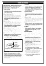
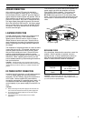
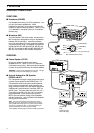
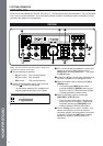
Connect your antenna feed line to ANT 1. If you are
using two antennas, connect the second antenna to
ANT 2. The EXT RX ANT jack can be used to connect
a separate receiver. Note that this jack must be
enabled by Menu configuration {pages 24, 27} before it
can be used.
CAUTION:
◆
Transmitting without first connecting an antenna or other
matched load may damage the transceiver. Always connect the
antenna to the transceiver before transmitting.
◆
Use a lightning arrestor to prevent fire, electric shock, or damage
to the transceiver.
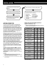
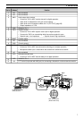
APPROX. LOSS (dB) PER 30 METERS (100 FEET) OF
CORRECTLY MATCHED 50 Ω LINE
• Use only as a general guide. Specifications may vary
between cable manufacturers.
6.4
2.6
2.3
2.3
2.1
2.0
1.4
1.2
1.0
0.90
0.90
0.72
0.70
0.68
0.54
0.45
0.48
0.40
0.39
0.32
0.26
4.3
1.6
1.5
1.5
1.4
1.0
0.93
0.80
0.80
0.60
0.60
0.50
0.48
0.48
0.37
0.33
0.29
0.26
0.25
0.21
0.16
2.3
0.75
0.80
0.65
0.70
0.50
0.45
0.38
N/A
0.29
0.29
0.24
0.24
N/A
N/A
N/A
0.13
0.12
< 0.10
< 0.10
< 0.10
RG-174, -174A
RG-58A, -58C
3D-2V
RG-58, -58B
RG-58 Foam
RG-8X
5D-2V
RG-8, -8A, -9, -9A, 9B,
-213, 214, 215
5D-FB
RG-8 Foam
8D-2V
10D-2V
9913
8D-FB
10D-FB
12D-FB
RG-17, -17A
1/2" Hardline
20D-2V
3/4" Hardline
7/8" Hardline
Transmission Line
3.5 MHz
14 MHz 30 MHz
N/A: Not available
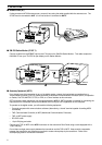
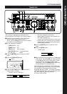
Connect all accessories to the transceiver {page 4}.
Accessories include the following:
• Microphone
• Antenna Tuner
• CW Key
• Computer
• TNC/ Multimode Communications
Processor
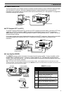
|nstall and connect an antenna system
{page 2}.
Install a ground system that satisfies DC
and RF grounding requirements {page 3}.
Install lightning protection to protect the
antenna system, your personal safety,
and your property {page 3}.
Install and connect a DC power supply {page 3}.
• Headphones
• External Speaker
• RTTY Equipment
• Linear Amplifier