


76
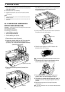
4 Unplug CN407 (wired to the
AT connector on the
Rear Panel) from the circuit board. Lift up Cover B,
and remove the small SO-2 board from the
compartment below.
5 Insert the SO-2 unit into the SO-2 board. Solder the
five pins on the unit to the board.
6 Slide the small switch on the SO-2 board in the
direction of the “SO-2” arrow.
Note:
This switch must be positioned correctly for the SO-2 unit to
function.
7 Re-install the SO-2 board in the transceiver in the
same location from which it was removed.
8 Re-position Cover B, install only 6 screws, and
replace CN407 that was unplugged in Step 4.
9 Re-position the speaker-bracket assembly, install its
screws (4 screws), and plug the speaker cable into
CN404.
10 Replace the top case and re-install its screws
(10 screws).
Note:
For more information, refer to the Instruction Manual provided
with the SO-2 unit.
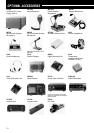
14 INSTALLING OPTIONS
5 Orient the VS-2 unit with the large IC (IC1) facing
down, then install this unit on the two threaded posts
using the 2 screws.
6 Re-install Cover A (7 screws).
7 Replace the bottom case and re-install its screws
(12 screws).
Note:
◆
For more information, refer to the Instruction Manual provided
with the VS-2 unit.
◆
The supplied screws and cushion are not used. Keep them for
future use.
SO-2 TEMPERATURE-COMPENSATED
CRYSTAL OSCILLATOR (TCXO)
CAUTION:
Switch OFF the power and unplug the DC power cable
before beginning installation.
EQUIPMENT REQUIRED:
• Large Phillips screwdriver
• Small Phillips screwdriver
• Pencil soldering iron (25 W)
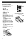
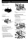
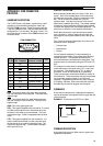
1 Remove the top case (10 screws).
2 Unplug the speaker cable from the 2-pin connector
CN404. Remove the speaker-bracket screws
(4 screws), then lift out the entire speaker assembly.
3 Remove the remaining screws (6 screws) from
Cover B.
Speaker-bracket screws
Speaker assembly
CN404
Cover B
SO-2 board
Cover B
S
O
-2
SO-2 unit
SO-2 board
SO-2