


KODAK EKTAGRAPHIC III Slide Projector 31
Appendix A
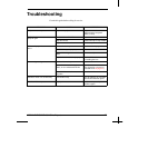
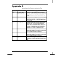
Special-Application Receptacle Identification Chart
Contacts Function Description
1 & 3 Zero-Position Switch
(Models A and E Plus)
Connects to an internal single-pole single-throw normally
open switch. Contacts are closed when the slide tray is at any
position other than zero. These leads connect only to the
switch terminals.
Do not exceed a switching load of 1 A at
30 V ac
.
4 & 5 Shutter Switch Connects to an internal single-pole single-throw normally
closed switch. Contacts are open when a slide is in the
projector gate and the shutter is open. These leads connect
only to the switch terminals.
Do not exceed a switching load
of 1 A at 30 V ac
.
7 & 8 Low-Voltage Supply For operating external equipment. The current is supplied by
a secondary winding on the main motor, isolated from the
line-voltage power, and is available whenever the main
projector motor is running. Supply is 25.5 V, 500 mA (1/2 A)
maximum. Contact number 8 is common (return) for the
remote-control circuit. Contact number 7 is the “hot” lead and
is fused with a slow-blowing fuse. (Replacement requires
disassembly of the projector by a qualified technician.)
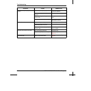
6 & 8 Forward Tray Connects to the forward tray-advance circuitry in the
projector. These contacts are connected internally to the
remote-control receptacle and an electrical connection made
at either receptacle will result in a forward cycle.
2 & 8 Reverse Tray Cycle Connects to the reverse tray-advance circuitry in the
projector. These contacts are connected internally to the
remote-control receptacle and an electrical connection made
at either receptacle will result in a reverse cycle.
Shell Plug Ground If a plug with a conducting shell is used, it is connected to the
projector frame (chassis) through the special-application
receptacle and to earth ground through the projector's power
cable.