


Main Unit Theory of Operation Fusing Section
2-101
II Composition/Operation
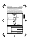
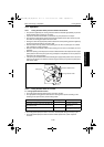
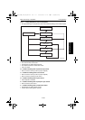
• Operation timing
1. The Fusing Motor (M4) is turned at low speed when the leading edge of the media
reaches a point before the roller pressure point.
2. When it is detected that the Paper Loop Sensor (PC6) is unblocked, the Fusing Motor
(M4) is turned at high speed. Regardless of the condition of the Paper Loop Sensor
(PC6), the Fusing Motor (M4) is kept turned at high speed for a predetermined period
of time after the motor speed has been switched to the high level.
3. When it is detected that the Paper Loop Sensor (PC6) is blocked, the Fusing Motor
(M4) is turned at low speed. Regardless of the condition of the Paper Loop Sensor
(PC6), the Fusing Motor (M4) is kept turned at low speed for a predetermined period of
time after the motor speed has been switched to the low level.
4. The operations of steps 2 and 3 above are repeated.
5. When the trailing edge of the media moves past the 2nd Transfer Roller, the speed con-
trol is terminated and thereafter the Fusing Motor (M4) is turned at the normal speed.
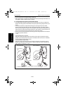
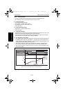
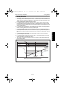
C. Fusing Pressure Roller deformation prevention control
• To prevent the Fusing Pressure Roller from being deformed, the Fusing Pressure Roller
is forcibly turned if it is left idle for a predetermined period of time.
• Operation timing
1. If the machine remains in the standby state for more than 13 hours, the Fusing Motor
(M4) is turned at 1/3 speed for 1 sec.
2. If the machine remains in the Power Save mode for more than 14 days, a single refer-
ence temperature adjustment is performed [during which the Fusing Cooling Fan Motor
(M11) is also turned] and thereafter the Fusing Motor (M4) is turned at 1/3 speed for 1
sec.
☞ 2-110
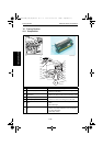
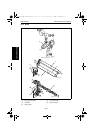
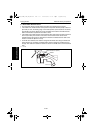
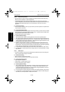
D. Media exit detection control
• The Exit Sensor (PC8) detects the media conveyed from the Fusing Belt and Fusing
Pressure Roller.
• The leading edge of the media pushes up the Exit Sensor actuator. When the actuator
blocks the Exit Sensor (PC8), the machine determines that the media has reached the
exit point.
• The Exit Sensor is placed right after the Fusing Pressure Roller in order to detect the
media jam and prevent the media from being wound to the Fusing Pressure Roller.
4138to2108c0
Actuator
Paper Size Sensor (PC8)
5430DL_5440DL_5450_TO_PDF.book 101 ページ 2005年4月12日 火曜日 午後4時49分