


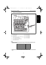

Main Unit Theory of Operation Print Head (PH)
2-5
II Composition/Operation
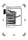
2.2.3 Laser emission timing
• When a Ready signal is detected after the lapse of a given period of time after the print
cycle has been started, a Laser ON signal is output from the Print Control Board (PWB-
P).
• The Laser ON signal triggers the firing of each laser light, which illuminates the SOS
Board via the Polygon Mirror, G1 Lens, Separation Mirror (K), and SOS Lens. This gen-
erates an SOS signal.
• This SOS (Start of Scan) signal unifies the timing at which the laser lights are irradiated
for each main scan line.
• The SOS signal is generated only from the K laser light. For the other colors, the emis-
sion timing is determined with reference to K.
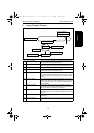
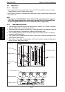
2.2.4 Laser emission area
A. Main scan direction (FD)
• The print start position in the FD direction is determined by the FD Print Start signal
(HSYNC) that is output from the Print Control Board (PWB-P) and the width of the
media.
• The laser emission area is determined by the media size.
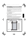
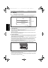
B. Sub scan direction (CD)
• The print start position in the CD direction is determined by the CD Print Start signal
(TOD) that is output from the Print Control Board (PWB-P) and the length of the media.
However, there is a 4 mm/0.157" wide void area on both edges of the media.
• The laser emission area is determined by the media size. However, there is a 4 mm/
0.157" wide void area on both the leading and trailing edges of the media.
4138to2595c0
Void width: 4 mm/0.157"
Void width: 4 mm/
0.157"
Void width: 4 mm/0.157"
Void width: 4 mm/
0.157"
5430DL_5440DL_5450_TO_PDF.book 5 ページ 2005年4月12日 火曜日 午後4時49分