


1st Transfer Section Main Unit Theory of Operation
2-42
II Composition/Operation
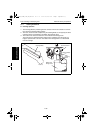
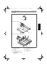
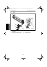
E. Retraction operation
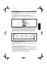
1. Rotation of the Intermediate Transport Motor (M3) is transmitted by a gear train to the
Pressure/Retraction Clutch/1st Image Transfer (CL4).
2. Rotation of the Pressure/Retraction Clutch/1st Image Transfer (CL4) turns the Pressure
Cam, which moves the Sliding Plate.
3. As the Sliding Plate moves, the Retraction Lever turns.
4. As the Retraction Lever turns, the 1st Transfer Roller is retracted from the Transfer Belt.
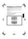
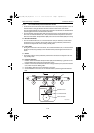
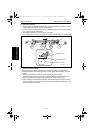
F. Pressure position control
• The pressure and retraction operation of the 1st Transfer Roller is controlled as the
Retraction Position Sensor/1st Image Transfer (PC9) detects the movement of the Slid-
ing Plate.
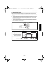
1. The Pressure/Retraction Clutch/1st Image Transfer (CL4) is energized.
2. The Sliding Plate is moved to press the 1st Transfer Rollers up against the Transfer
Belt, which blocks the Retraction Position Sensor/1st Image Transfer (PC9).
3. After the lapse of a predetermined period of time after the Retraction Position Sensor/
1st Image Transfer (PC9) has been blocked, the Pressure/Retraction Clutch/1st Image
Transfer (CL4) is de-energized.
4138to2045c1
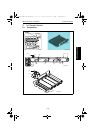
Sliding Plate Pressure Cam
Retraction Lever
1st Transfer Roller
Photo Conductor
5430DL_5440DL_5450_TO_PDF.book 42 ページ 2005年4月12日 火曜日 午後4時49分