


C.2. RS-232C/RS-422A Interface
C-4
C.2. RS-232C/RS-422A Interface
RS-232C interface
Interface Signals
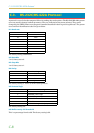
The pins of the printer's RS-232C interface connector carry the signals listed in Table C.2. The table also
indicates whether each signal is incoming or outgoing with respect to the printer.
Brief descriptions of the signals follow.
FG - Frame Ground - (Pin 1)
This pin is connected directly to the printer frame.
TXD - Transmit Data - (Pin 2)
This output carries asynchronous data sent by the printer to the computer. It is used mainly in handshaking
protocols.
RXD - Receive Data - (Pin 3)
This input carries serial asynchronous data sent by the computer to the printer.
RTS - Request To Send - (Pin 4)
This output is always held high (above 3 volts).
CTS - Clear To Send - (Pin 5)
DSR - Data Set Ready - (Pin 6)
Unused.
SG - Signal Ground - (Pin 7)
All signals can transmit between the printer and the host computer to send each signals with a signal
ground.
DTR - Data Terminal Ready - (Pin 20)
This output is used as a buffer nearly-full handshake line. It is held high (above 3 volts) when the buffer can
accept more data.
RS-232C Interface Voltage Levels
The voltage levels of the interface signals conform to EIA RS-232C specifications. SPACE is from 3 volts to
15 volts. MARK is from -3 volts to -15 volts. Voltages between -3 volts and 3 volts are undefined.
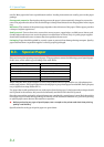
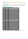
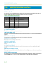
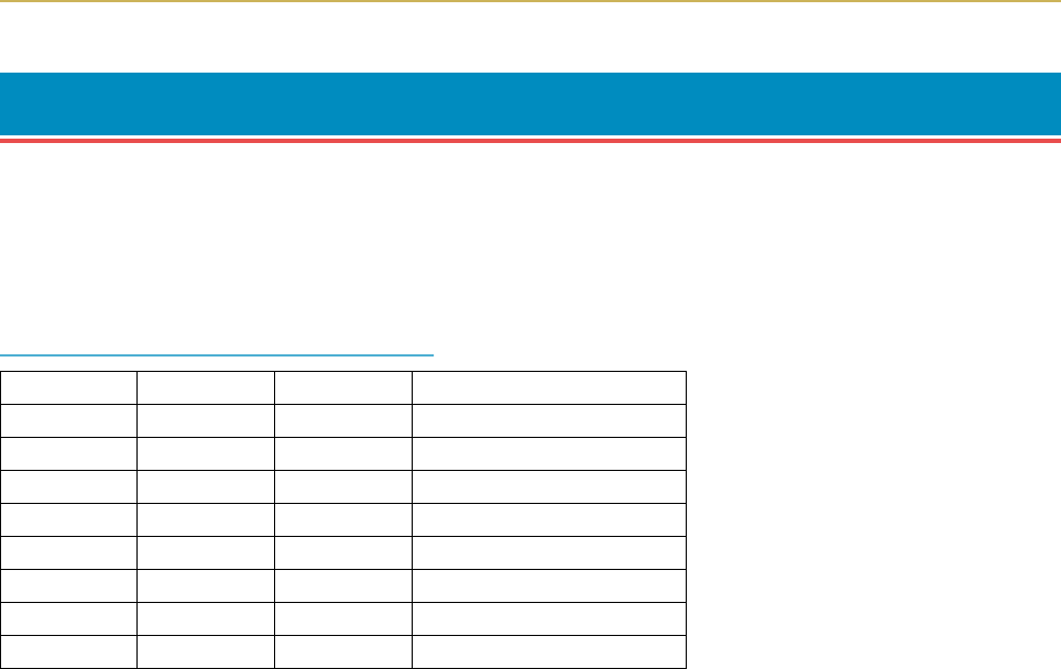
Table C.2. RS-232C Signal Pin Assignments
Pin In/out Signal Description
1 – FG Frame ground
2 Out TXD Transmit Data
3 In RXD Receive Data
4 Out RTS Request To Send
5 In CTS Clear To Send
6 In DSR Data Set Ready
7 – SG Signal Ground
20 Out DTR Data Terminal Ready