


C.2. RS-232C/RS-422A Interface
C-7
Interface Signals
The pins in the printer's RS-422A interface connector carry the signals listed in Table C.3.
Overview of Signals (RS-422A)
FG - Frame Ground - (Pin 1)
This pin is connected directly to the printer frame.
SG - Signal Ground - (Pin 7)
All signals can transmit between the printer and the host computer to send each signals with a signal
ground.
RDB - Receive Data - (Pin 18)
RDA - Receive Data Inverted - (Pin 3)
These pins carry asynchronous data sent from the computer to the printer. (differential input)
SDB - Send Data - (Pin 10)
SDA - Send Data Inverted - (Pin 9)
These pins carry asynchronous data sent from the printer to the computer. (differential output)
RS-422A interface voltage levels
The interface signal voltage levels conform with the EIA RS-422A standard. The differential voltage varies
from 200 mV to 6V.
SERIAL Connector
The connector marked "IOIOI" (RS-232C/RS-422A) on the rear panel is a DB-25S connector. Use a DB-25P
connector (or equivalent) for the connector on the cable.
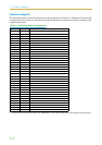
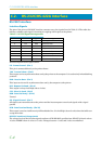
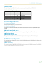
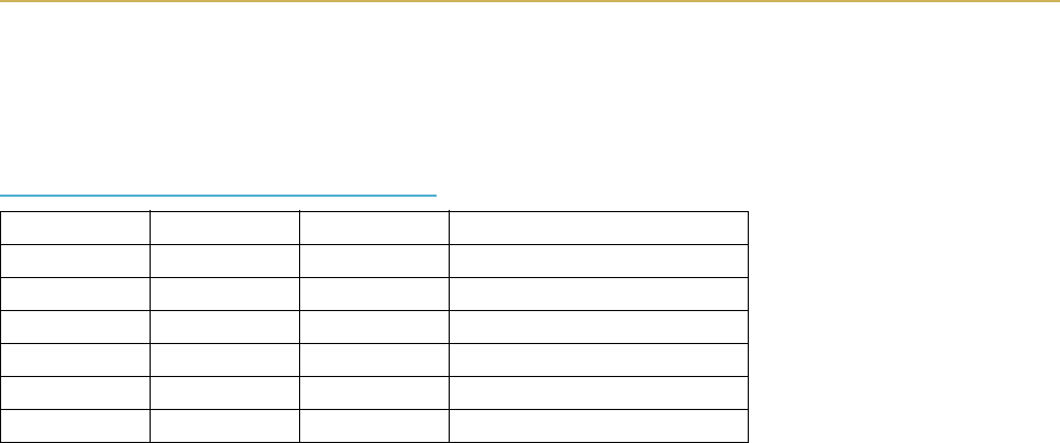
Table C.3. RS-422A Signal Pin Assignments
Pin In/out Signal Description
1 – FG Frame ground
3 In RDA Receive data Inverted
7 – SG Signal ground
9 Out SDA Send data Inverted
10 Out SDB Send data
18 In RDB Receive data