


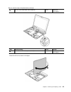
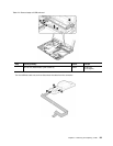
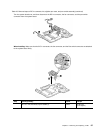
Table 25. Removal steps of LCD assembly (continued)
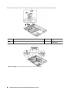
When installing: Route the antenna cables along the cable guides and secure them with the tapes. As you route the
cables, make sure that they are not subjected to any tension. Tension could cause the cables to be damaged by
the cable guides, or a wire to be broken.
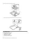
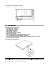
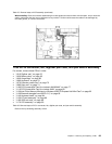
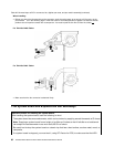
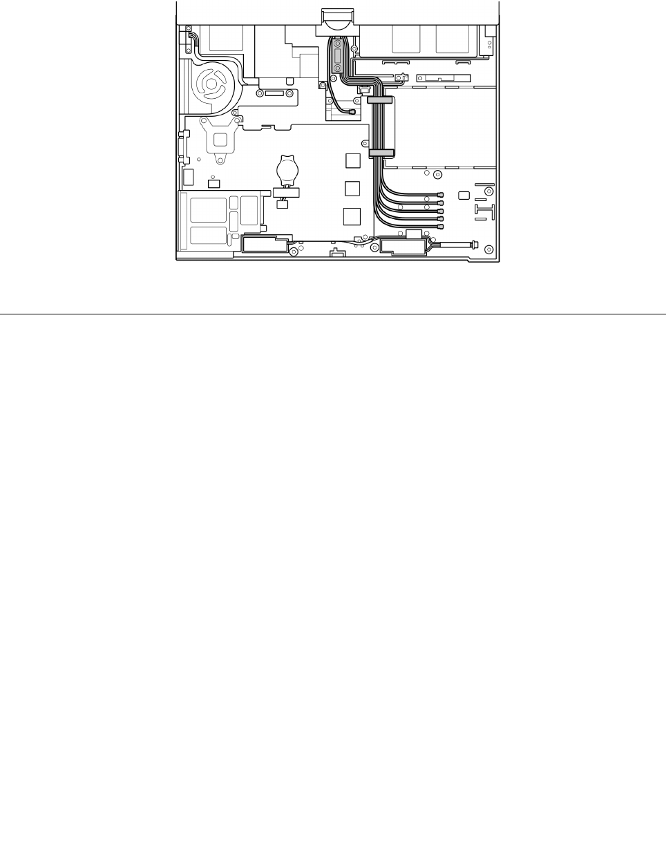
1180 DC-in connector, fan, digitizer pen case, and pen switch assembly
For access, remove these FRUs in order:
• “1010 Digitizer pen” on page 63
• “1020 Battery pack” on page 63
• “1050 Hinge caps” on page 69
• “1060 Keyboard” on page 70
• “1070 Extension cable card” on page 73
• “1080 Palm rest” on page 74
• “1100 PCI Express Mini Card for wireless LAN/WiMAX” on page 77
• “1110 PCI Express Mini Card for wireless WAN” on page 80
• “1120 Intel Turbo Memory Minicard or Wireless USB PCI Express Half-Mini Card” on page 82
• “1130 Bluetooth daughter card (BDC-2.1)” on page 83
• “1140 Keyboard bezel” on page 84
• “1150 I/O card assembly” on page 86
• “1160 USB sub card” on page 88
• “1170 LCD assembly” on page 90
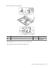
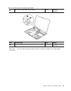
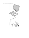
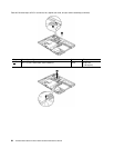
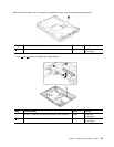
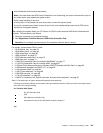
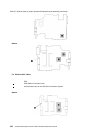
Table 26. Removal steps of DC-in connector, fan, digitizer pen case, and pen switch assembly
Remove the top shielding assembly at rst.
Chapter 8. Removing and replacing a FRU 93