


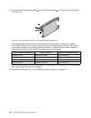
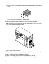
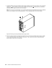
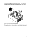
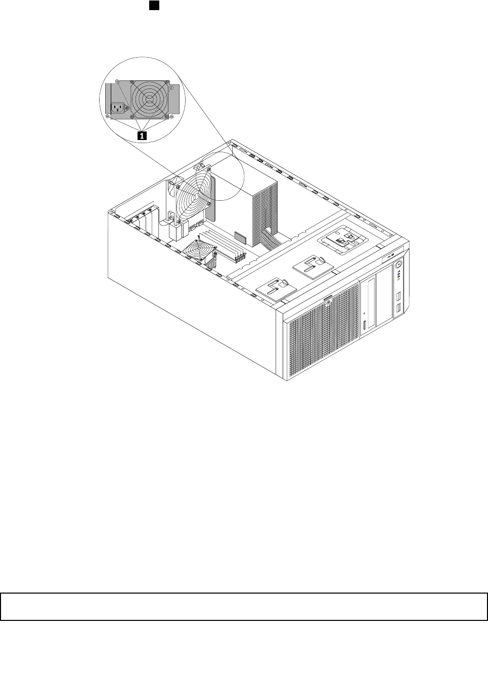
10. Install the new power supply assembly into the chassis so that the four screw holes in the new power
supply assembly are aligned with the corresponding holes marked with A in the rear of the chassis.
Then, install the four screws 1 to secure the new power supply assembly in place.
Note: Use only screws provided by Lenovo.
CPU
MEM
Figure79. Installing the non-hot-swap power supply assembly
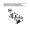
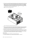
11. Refer to your note and connect the new power supply assembly cables to the system board, all drives,
and or hot-swap hard disk drive backplane(s), depending on the model. Then, properly route the cables
and secure the cables with the cable clips and ties in the chassis.
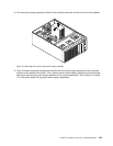
12. Reinstall the front system fan(s). See “Replacing the front system fan” on page 149.
13. If you are instructed to return the old non-hot-swap power supply assembly, follow all packaging
instructions and use any packaging materials that are supplied to you for shipping.
What to do next:
• To work with another piece of hardware, go to the appropriate section.
• To complete the replacement, go to “Completing the parts replacement” on page 168
.
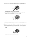
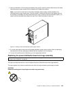
Replacing a hot-swap redundant power supply module
Attention: Do not open your server or attempt any repair before reading and understanding the “Safety information”
on page iii and “Guidelines” on page 83.
140 ThinkServer Hardware Maintenance Manual