


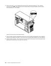
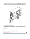
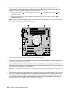
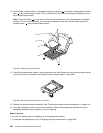
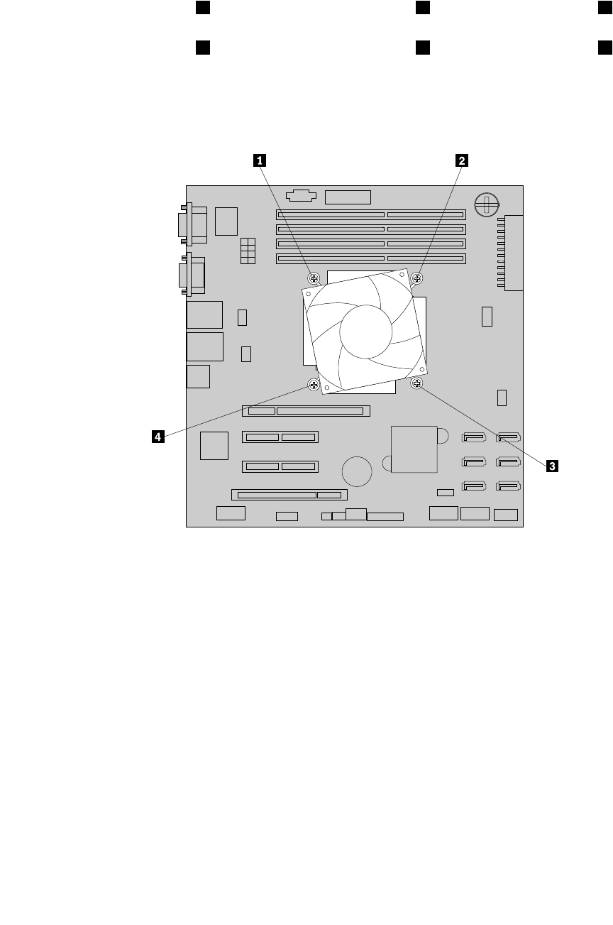
6. Remove the four screws that secure the heat sink and fan assembly to the system board. It is
recommended that you carefully remove the four screws from the system board using the following
method to avoid any possible damage to the system board.
a. Partially remove screw 1 , then completely remove screw 3 , and then return to screw 1 and
completely remove it.
b. Partially remove screw 2 , then completely remove screw 4 , and then return to screw 2 and
completely remove it.
Note: The four screws are integrated parts of the heat sink and fan assembly. Do not try to remove the
four screws from the heat sink and fan assembly.
Figure90. Removing the screws that secure the heat sink and fan assembly
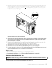
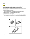
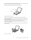
7. Gently twist the heat sink and fan assembly to free it from the microprocessor and then lift the heat sink
and fan assembly off the system board.
8. Lay aside the old heat sink and fan assembly. Touch the static-protective package that contains the new
heat sink and fan assembly to any unpainted surface on the outside of the server. Then, remove the new
heat sink and fan assembly from the package.
Note: When handling the heat sink and fan assembly, do not touch the thermal grease on the bottom of
it.
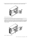
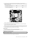
9. Place the new heat sink and fan assembly on the system board so that the four screws on the new heat
sink and fan assembly are aligned with the corresponding mounting studs on the system board. Note
the orientation of the new heat sink and fan assembly and make sure that you properly place it so that
you can easily connect the heat sink and fan assembly cable to the microprocessor fan connector on
the system board. See “System board components” on page 42
.
156 ThinkServer Hardware Maintenance Manual