


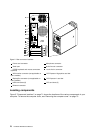
Internal drives are installed in bays. In this manual, the bays are referred to as bay 1, bay 2, and so on. Figure
5 “Drive bay locations” on page 73 shows the locations of the drive bays.
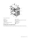
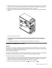
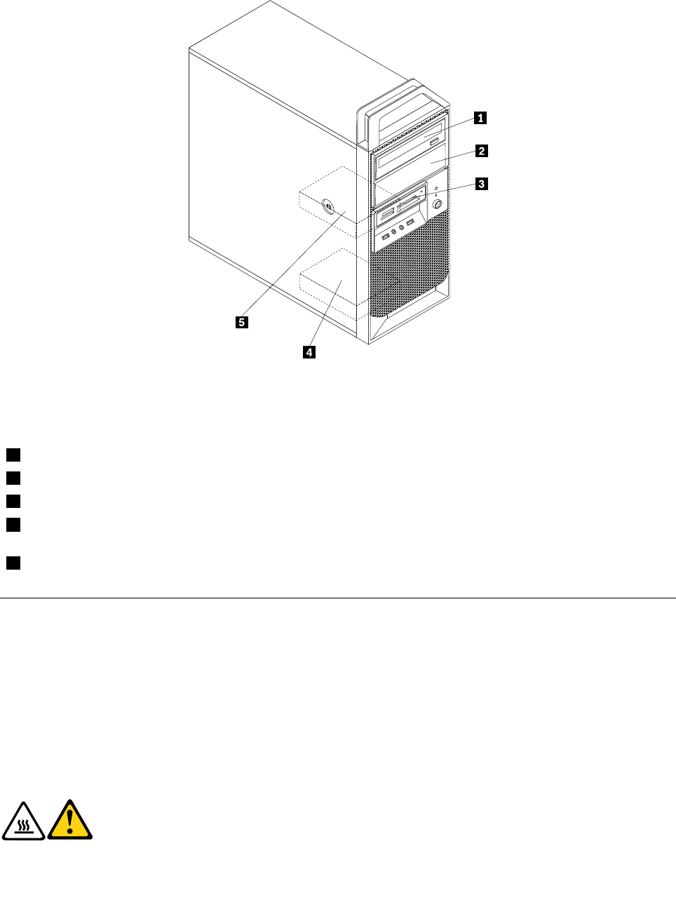
Figure 5. Drive bay locations
The following list describes the type and size of the drive that you can install in each bay:
1 Bay 1 - Maximum height: 43.0 mm (1.7 inches) Optical drive
2 Bay 2 - Maximum height: 43.0 mm (1.7 inches) Optical drive
3 Bay 3 - Maximum height: 25.8 mm (1.0 inch) 3.5-inch card reader (installed in some models)
4 Bay 4 - Maximum height: 25.8 mm (1.0 inch) 3.5-inch secondary SATA hard disk drive
(installed in some models)
5 Bay 5 - Maximum height: 25.8 mm (1.0 inch) 3.5-inch primary SATA hard disk drive
Removing the computer cover
Attention
Do not open your computer or attempt any repair before reading and understanding the “Important safety
information” in the ThinkStation Safety and Warranty Guide that came with your computer. To obtain a copy
of the ThinkStation Safety and Warranty Guide, go to:
http://www.lenovo.com/support
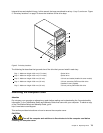
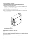
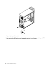
This section provides instructions on how to remove the computer cover.
CAUTION:
Turn off the computer and wait three to ve minutes to let the computer cool before
removing the computer cover.
Chapter 9. Replacing FRUs 73