


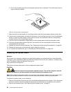
d. Do not drop anything onto the microprocessor socket while it is exposed. The socket pins must be
kept as clean as possible.
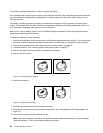
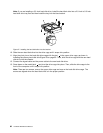
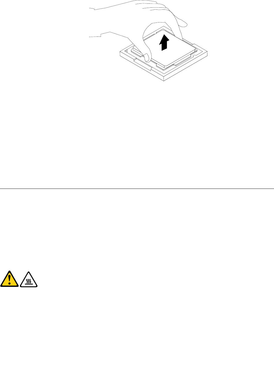
Figure 22. Removing the microprocessor
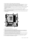
7. Make sure that the small handle is in the raised position and the microprocessor retainer is fully open.
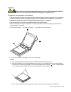
8. Hold the new microprocessor and align the notches on it with the alignment keys in the microprocessor
socket, or align the small triangle on one corner of the new microprocessor with the corresponding
beveled corner of the microprocessor socket.
9. Lower the new microprocessor straight down into the microprocessor socket on the system board.
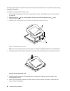
10. Close the microprocessor retainer and lock it into position with the small handle to secure the new
microprocessor in the socket.
11. Reinstall the heat sink and fan assembly. See “Replacing the heat sink and fan assembly” on page 85.
12. Reinstall any other parts or reconnect any other cables you removed.
13. To complete the replacement, go to “Completing the FRU replacement” on page 103.
Replacing the system board
Attention
Do not open your computer or attempt any repair before reading and understanding the “Important safety
information” in the ThinkStation Safety and Warranty Guide that came with your computer. To obtain a copy
of the ThinkStation Safety and Warranty Guide, go to:
http://www.lenovo.com/support
This section provides instructions on how to replace the system board.
CAUTION:
The heat sink and microprocessor might be very hot. Turn off the computer and wait
three to ve minutes to let the computer cool before removing the computer cover.
Note: When replacing the system board, you must order a new retention module for the new system board.
Make sure you have a retention module for the new system board before continuing this procedure.
To replace the system board, do the following:
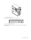
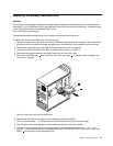
1. Remove all media from the drives and turn off all attached devices and the computer. Then, disconnect
all power cords from electrical outlets and disconnect all cables that are connected to the computer.
2. Remove the computer cover. See “Removing the computer cover” on page 73.
88 Hardware Maintenance Manual