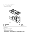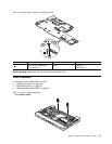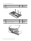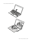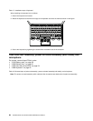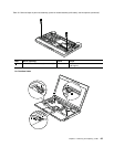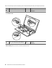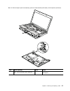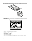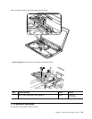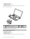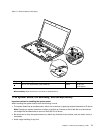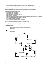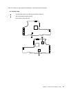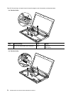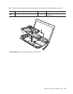
Table 18. Removal steps of palm rest assembly, power-on board assembly (with cable), and microphone (continued)
1
2
When installing: Make sure that all the projections of the palm rest assembly are attached rmly to the guide
holes of the base cover.
1100 CRT board assembly (with cable)
For access, remove these FRUs in order:
• “1010 Battery pack” on page 50
• “1020 Bottom door” on page 51
• “1030 Hard disk drive (HDD)” on page 54
• “1080 Keyboard” on page 61
• “1090 Palm rest assembly, power-on board assembly (with cable), and microphone” on page 64
68 ThinkPad X100e and X120e Hardware Maintenance Manual


