


Touch Screen Display
109
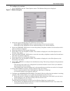
5. Select DELAY.
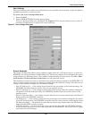
A keypad is displayed prompting you for a delay time, in seconds, for a condition to exist before
the alarm is triggered.
6. Enter the delay value. The range for the values are from 0 (zero) to 99.9 seconds.
7. Select OK on the keypad to keep your setting.
The value you entered is displayed in the field adjacent to the corresponding input contact.
8. Repeat Steps 2 to 7 for each input contact.
9. Select SAVE after you have configured all input contacts.
Be sure to select Save even if you have accessed this dialog only to change a setting.
10. Enter the settings in Table 32 - Input contact isolator settings record.
This information is not saved if control power is removed.
11. Select OK in the Comm Options dialog box to activate the settings.
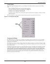
Configuring the Programmable Relay Board Settings
The STS2/PDU can contain up to two programmable relay boards (PRB) that can trigger an external
device when an event occurs in the Static Transfer Switch 2 Power Distribution Unit. For example, if
Source 1 fails, an external light flashes.
See 6.1 - Programmable Relay Board for more information on the PRBs.
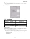
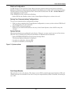
The programmable relay board dialog box with two options: STANDARD SET and USER DEFINED
SET. The STANDARD SET are the factory-configured settings.
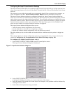
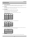
The STANDARD SET for the programmable relay board settings are:
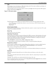
The USER DEFINED SET allows you to assign faults and alarms to each contact on the relay boards.
Utilizing the USER DEFINED SET, you can also select Input Contact Isolators to associate with a
programmable relay.
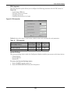
In addition individual events, three other assignment choices are available:
• SELECT ALL sends a summary event to the selected relay whenever any event occurs. If this set-
ting is selected for a relay, no other event needs to be assigned for that relay.
• ON SOURCE 1 or ON SOURCE 2 can be assigned to a relay to send a notification when that
source is being used by the load.
Once configured, the Static Transfer Switch 2 Power Distribution Unit continuously checks the status
of the items defined for each contact and updates the state of the relay.
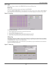
Table 19 Standard settings for programmable relays
Relay Setting Definition
1 SOURCE 1 FAIL Source 1 failure
2 SOURCE 2 FAIL Source 2 failure
3 BYPASS CB4 CLOSED Switch (CB4) is closed; Source 1 is bypassed.
4 BYPASS CB5 CLOSED Switch (CB5) is closed; Source 2 is bypassed.
5 TRANSFER INHIBIT A transfer between Source 1 and Source 2 is being restrained.
6 OUT OF SYNC
The phase difference between sources 1 and 2 exceeds the
allowable threshold for transfer.
7 EQUIP OVER TEMP
The ambient temperature of the ProductName
exceeds the
recommended threshold for operation.
8 Blank No setting