


Power and Control Wiring
8
4.0 POWER AND CONTROL WIRING
All power and control wiring must be installed by a licensed, qualified electrician. All power and con-
trol wiring must comply with the National Electrical Code and all applicable local codes. Unless oth-
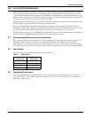
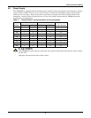
erwise labeled, use the recommended tightening torque shown in Table 29.
The input power busbars are accessible through the front of the unit. Liebert’s 250A units have PEM
nut inserts designed to allow one-handed tightening. Busbars in the 400-800A units are supplied with
holes to accommodate two-hole lugs.
Cables can be installed through the top or bottom of the unit through removable conduits plates.
Units with output inline panelboards are bottom exit only for output cables.
See Figures 12 through 21 for wiring entrance locations.
4.1 Input and Output Power Connections
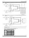
The input power connections are made to the busbars provided inside the unit (see Figures 26
through 31). These busbars are accessible through the front of the unit.
Output power connections are handled two different ways, depending on the type of distribution used.
Power connections on standard units with an output breaker are made to the busbars inside the unit.
These busbars are accessible through the front on 250A units and on the side on 400-800A units. See
Figures 26 through 31 for details on the busbars. Power connections on units with panelboard distri-
bution are made directly to the panelboard breakers. Busbars are provided in the output cabinet for
ground and neutral connections.
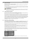
The two input power feeds (sources) to the STS2/PDU should be from two independent sources to
avoid a common source failure.
To ensure proper operation of the STS2/PDU, the two input sources must be the same nominal volt-
age level and phase rotation.
For uninterrupted automatic transfer, the two input sources should be synchronized within
15 degrees.
The STS2/PDU is designed for operation with 3-wire, solidly grounded sources only.
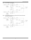
See Figures 3 through 6 for typical one-line diagrams. Refer to Figures 26 through 31 for electrical
field connections on all units.
!
WARNING
Verify that all input power and control circuits are de-energized and locked out before making
connections inside unit.
!
CAUTION
The input sources to the STS2/PDU must be grounded-wye sources. Input sources other than
solidly grounded-wye sources may cause damage to the switch.