


Alarms and Faults
85
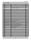
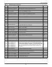
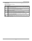
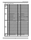
Table 12 Event messages
ID Alarm Message Description/Cause Action
1 S1 SCR SHORT One or more of the SCRs for Source 1 have shorted and failed. D, F, A, E
2 S2 SCR SHORT One or more of the SCRs for Source 2 have shorted and failed. D, F, A, E
3 S1 SCR OPEN One or more of the SCRs for Source 1 is open. D, F, A, E
4 S2 SCR OPEN One or more of the SCRs for Source 2 is open. D, F, A, E
5 PRIMARY FAN FAIL
A primary cooling fan has failed and the unit is now being cooled by a
secondary fan, which is not monitored.
D, A, E
6 CONTROL MODULE FAIL Control logic module has failed. D, A, E
7 PWR SPLY DC A FAIL Power supply DC bus A has failed. D, A, E
8 PWR SPLY DC B FAIL Power supply DC bus B has failed. D, A, E
9 PWR SPLY S1 AC FAIL Power supply Source 1 AC has failed. D, A, E
10 PWR SPLY S2 AC FAIL Power supply Source 2 AC has failed. D, A, E
11 PWR SPLY LOGIC FAIL A power supply module has failed. D, A, E
12 OUT VOLT SENSE FAIL The output volt sense module failed D, A, E
13 S1 VOLT SENSE FAIL The Source 1 volt sense module failed. D, A, E
14 S2 VOLT SENSE FAIL The Source 2 volt sense module failed. D, A, E
15 S1 SCR SENSE FAIL The Source 1 SCR sense module failed. D, A, E
16 S2 SCR SENSE FAIL The Source 2 SCR sense module failed. D, A, E
17 S1 CURR SENSE FAIL The Source 1 SCR current module failed. D, A, E
18 S2 CURR SENSE FAIL The Source 2 SCR current module failed. D, A, E
19 S1 GATE DRIVE FAIL The Source 1 gate drive module failed. D, A, E
20 S2 GATE DRIVE FAIL The Source 2 gate drive module failed. D, A, E
21 INTERNAL COMM FAIL Internal CAN communications failed. D, A, E
23 CB1 SHUNT TRIP FAIL CB1 shunt trip failed. D, A, E
24 CB2 SHUNT TRIP FAIL CB2 shunt trip failed. D, A, E
27 EQUIPMENT FAN FAIL One of the equipment fans failed D, A, E
28 INPUT 1 SURGE FAIL Source 1 input surge suppression module failed D, A, E
29 INPUT 2 SURGE FAIL Source 2 input surge suppression module failed D, A, E
64 HEATSINK OVERTEMP Heatsink has exceeded the recommended temperature. A, E
65 EQUIPMENT OVERTEMP Cabinet has exceeded the recommended temperature A, E
67 S1 UV Source 1 under voltage, fast detection. A, E
68 S1 UV (RMS) Source 1 under voltage, slow detection. A, E
69 S1 OV Source 1 over voltage A, E
70 S1 OF/UF Source 1 over frequency/under frequency A, E
71 S1 FAIL Source 1 failure. A, E
72 S2 UV Source 2 under voltage, fast detection. A, E
73 S2 UV (RMS) Source 2 under voltage, slow detection. A, E
74 S2 OV Source 2 over voltage. A, E
75 S2 OF/UF Source 2 over frequency/under frequency. A, E
76 S2 FAIL Source 2 failure. A, E
77 S1 OVERCURRENT Source 1 over current. A, E
78 S2 OVERCURRENT Source 2 over current. A, E
79 S1 I-PEAK I-PK on Source 1. D, F, A, E
80 S2 I-PEAK I-PK on Source 2. D, F, A, E