Chapter 3 Electrical Assembly
29
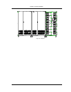
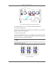
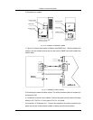
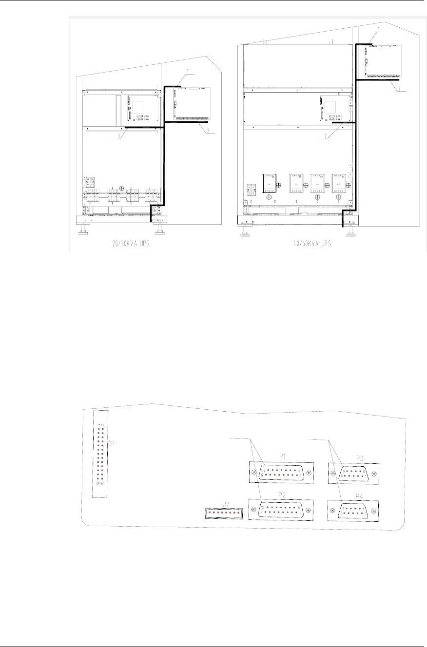
Fig. 3-6 Layout of signal cables of 20/30/40/60kVA UPS
2. Connection method
1.Parallel connection method
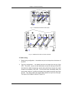
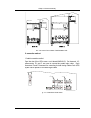
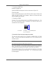
Open the door of the UPS to see a circuit board ULW2L61M3. On the board, 15-
pin connectors P1 and P2 are used to connect the parallel logic cables. 9-pin
connectors P3 and P4 are used for connecting the load sharing cables. Each UPS
system has two pieces of 15 meters length cables.
Parallel logic cable
Parallel load sharing cable
Fig. 3-7 Parallel Board ULW2L61M3


