Chapter 6 Maintenance
73
6.1.7 Monitoring system
1. Background communication
The monitoring system of this UPS system provides one RS232 port and one
RS485 port (the definition of the port is in Section 3.4.3), several input and output
dry contacts (refer to Section 3.4.4). The user can introduce the signal to the
nearest management office to conduct equipment management. All the data
displayed on the panel will be monitored by background monitoring software.
Besides, there are also MODEM and SNMP cards, which are used for MODEM and
SNMP communication.
1
)
RS232 mode
The transmission distance of RS232 mode is shorter than 15m. This RS232
mode is suitable for the short distance monitoring required by UPS operator or
user.
2
)
RS485 mode
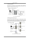
The J23 connector on the monitoring board is used for user’s RS485 port.
“485+” and “485-” are used as the user’s positive terminal and negative terminal
respectively. SHIELD terminal is used as the shielding terminal that connects the
shielding layer.
The transmission distance is shorter than 1000m. The user can use any
RS485/RS232 converter(such as the OCI-6 provided by us) to realize
networking of RS485+RS232 mode.
3)MODEM mode
The user can monitor the UPS remotely via a MODEM and the monitoring
software- POWERSTAR by dialing the preset telephone number. Refer to
“Directions of MODEM” and “Directions of POWERSTAR” for details.
4)SNMP mode
The parts of SNMP card UF-SNMP111 is compatible with 10/100M either net.
The SNMP card supports various kinds of protocols of SNMP, TFTP, HTTP and
TELNET and providing a solution for high speed network access method.
The user can connect the UPS to the LAN through the SNMP card and realize
the network management.
Refer to “Directions of SNMP” card for details.


