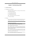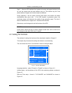
Chapter 5 Operation of Display Panel
44
2001-11-08
UL33-0400L
12:50:30
Äæ±ä¿ªÆô ² ¢»ų́Êý 2/4
Ïàµçѹ V
µç Á ÷ A
Ƶ  ÊHz
A(B)
B(C) C(A)
221
11.8
12.3
50.2
50.1
50.1
0.99
0.99
ÊäÈë¿Õ¿ª±ÕºÏ
11£ -08 12:09
Êä³ö¿Õ¿ª±ÕºÏ
Ö÷·Äæ±ä¹©µç
µç³Ø¾ù³ä
11£ -08 12:09
11£ -08 12:09
11£ -08 12:15
11£ -08 12:12
F1
F2
F3
F4
Emergency
shutdown
Inverter
stare
Inverter
stop
Fault
clearing
Mute
Ö÷·ÊäÈë
ÅÔ·ÊäÈë
½»Á÷Êä³ö
±¾»ú¸ºÔØ
²¢»ú¸ºÔØ
µç³ØÊý¾Ý
¹¦ÂÊÒòÊý
Ïßµçѹ V
220 221
381 380 382
Battery
indicator
Bypass
indicator
Inverter
indicator
Load
indicator
Rectifier
indicator
Alarm
indicator
Alarm
2001-11-08
UL33-0400L
12:50:30
Inv. On Units 2/4 ID: 1
Input Breaker Closed
11£ -08 12:09
UPS in Battery Mode
Battery low
11£ -08 12:09
11£ -08 12:28
11£ -08 12:28
11£ -08 12:50
Records
Out
System
Local
Settings
Byp. Breaker Closed
Mains Volt. Abnormal
Battery
Chinese
Chinese
English
Com. Adress Set
1
1
Date & Time Set
2001£ -11£ -08 12:50:30
Language
m
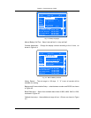
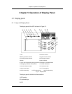
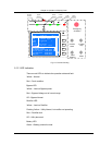
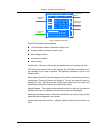
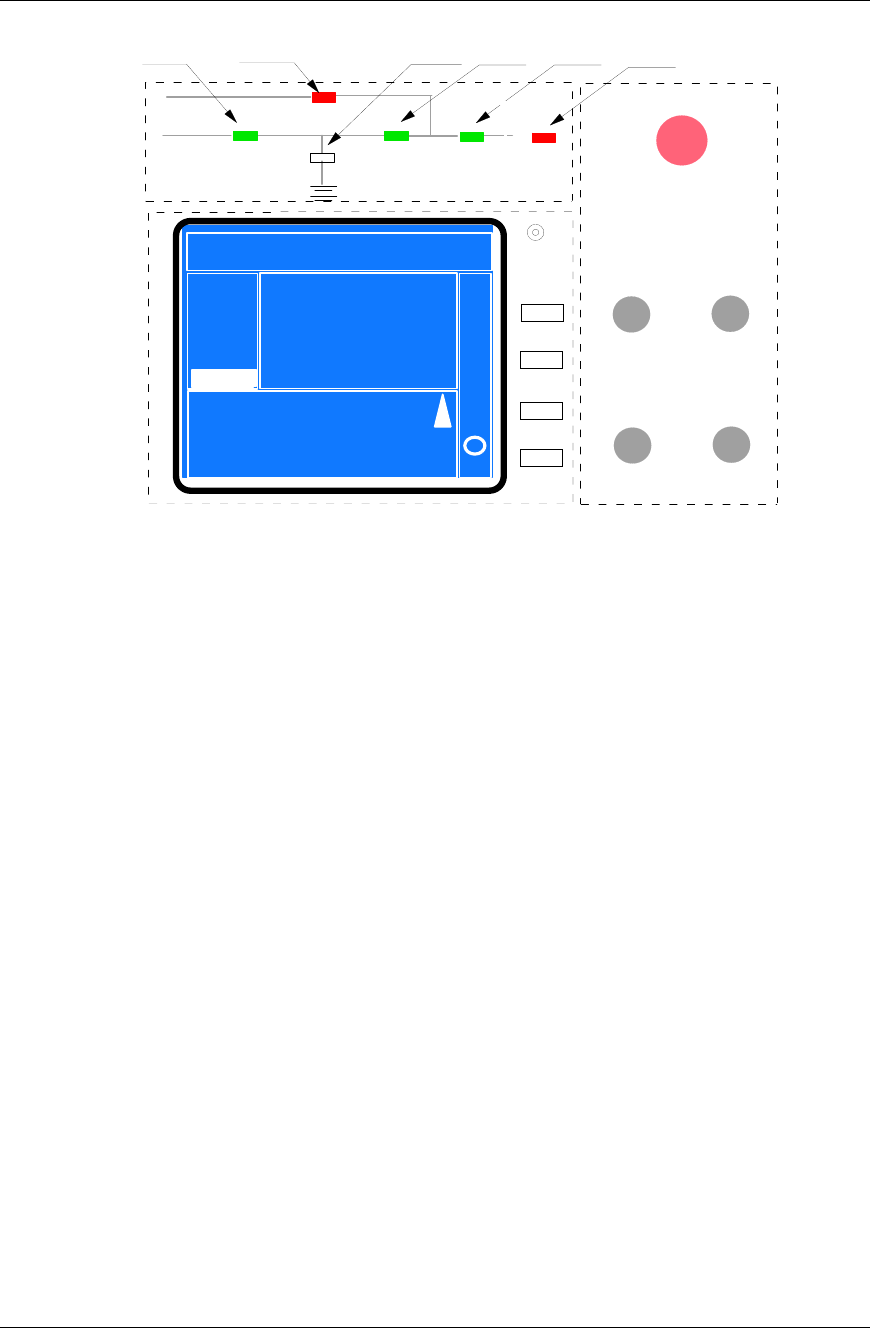
Fig. 5-2 Function Dividing
5.1.2 LED Indication
There are six LEDs to indicate the operation state and fault.
Yellow – Normal
Red – Fault condition
Bypass LED
Yellow – Load on Bypass power
Red – Bypass Voltage out of normal range
Off – Bypass Normal
Rectifier LED
Yellow – Load on Rectifier
Flashing Yellow – Utility Normal, but rectifier not operating
Red – Rectifier fault
Off – Utility abnormal
Battery LED
Green – Battery powers the load


