


Index-6 SP Switch Router Adapter Guide - 1.4 Update 2
Index
R
power supplies
redundant AC units, 1-4
safely powering off, 1-4
POWER-UP, state of, 2-37
primary node, SP Switch, 1-2
processor node, SP Switch, 1-2
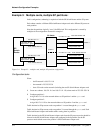
single partition example, C-2
profiles
changing Card variables, 2-24
changing Dump variables, 2-28
changing Load variables, 2-27
R
receive port, states (LEDs), 1-11
redundant AC power supplies
caution when unplugging, 1-4
replacing a card, 1-7
reset process, 2-38
resetting SP Switch Router Adapter card,
2-23
revision number, card location, 1-7
RMS (router management system)
data collection via grdinfo, 3-25
route command, 3-6
route table entries
viewing with netstat -rn, 3-8
routing statistics, via netstat -rs, 3-9
routing, memory needed, 1-5
RS/6000 SP Switch Router
based on GRF router, 1-1
connection to SP system, 1-2
features, 1-2
media types supported, 1-2
RUNNING, state of, 2-37
run-time code
change default in Card profile, 2-25
S
saving config files, grwrite, 3-5
serial daughter card, 1-7
serial number, card location, 1-7
setver command, 3-5
sh command, 2-22
shell
how to establish for SP Switch Router
session, 2-22
slot 66 (default), 3-4
slot number
in grreset command, 2-38
in ping command, 2-36
SMIT panels
for card configuration, 2-21
for dependent node configuration, 2-12
SNMP
community name, 1-17
configuration procedure, 2-18
mib2d activity, 1-17
starting SNMP daemon, 2-20
traps, 1-17
writes to grdev1.conf, 2-32
SNMP implementation, 1-15
card state descriptions, 1-16
how daemon starts up, 1-18
ibmSPDepNode MIB, 1-15
snmpd, configuration, 1-17
software, upgrade information, D-1
SP control workstation
access to SP Switch Router, 2-2
Ethernet cable to SP Switch Router, 1-4
obtaining Router host name, node number,
2-14
SNMP on router, 1-15
using Eunfence or Estart, 2-41
SP frame, determining, 2-12
SP node partitions, C-2
SP processor nodes, in networks
see Appendix C
SP SNMP Manager, 2-2
configuration tool, 2-21
mib2d interactions, 1-18
requirements, 1-17
SP Switch
assignments to multiple frames, 2-15
attaching cable to SP Switch Router, 2-10
cable connector end, illustrated, 1-6
cable required for SP Switch Router, 1-3
diagram of SP Switch Router connectivity,
2-2
display route table, 3-21
network examples, see Appendix C
SP Switch network, 3-6
SP Switch network configuration, see
Appendix C
SP Switch port, determining, 2-12
SP Switch Router
connection options, 1-3
Ethernet cable required, 1-4
general features, 1-2
ground strap, 1-4
host name assignment, 2-12
management commands, 3-2