


Installation and Configuration Steps
1-4 INA Module Installation and Configuration Guide
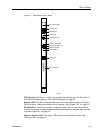
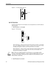
Ethernet Port. This RJ-45 connector provides a 10BaseT Ethernet connection. See
“Connect an Ethernet Cable” on page 3-4.
Ethernet Link LED. This green LED indicates link integrity to a 10BaseT hub. See
“Ethernet LEDs” on page 3-6.
Reboot Button. This button resets the router hardware and reboots ComOS. It has no
effect on MERLIN MAGIX voice operation. You will need a thin object such as a
straightened paper click to activate this recessed switch.
T1/PRI Connection. This RJ-45 connector connects the T1/PRI line. See “Connect a
T1/PRI Cable” on page 3-3.
DS-1 Test Jacks. There are three pairs of jacks for DS-1 troubleshooting. See “Using
the DS-1 Test Jacks” on page A-5.
Installation and Configuration Steps
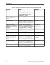
1. Collect information about your T1 or PRI line.
See “T1/PRI Provisioning” on page 2-1 for a preview of the values you need.
2. Collect information about the network and routing configuration.
See “Network Settings” on page 2-2 for a preview of the values you need.
3. Install the INA module in the MERLIN MAGIX system.
See “Install the INA Module in a Carrier” on page 3-1.
4. Configure the T1 or PRI line using the MERLIN MAGIX console.
See “Set Up T1/PRI on the MERLIN MAGIX” on page 2-1.
5. Assign data channels to the router using the MERLIN MAGIX console.
See “Assign T1/PRI Channels” on page 2-2.
6. Connect the INA module front panel cables.
See “Connect Cables” on page 3-1.
7. Configure the INA module.
See one of the following:
– “Using the INAWizard” on page 4-1.
– “Using the Command Line Interface” on page 5-1.
– “Using PMVision” on page 6-1.