


Connect Cables
3-2 INA Module Installation and Configuration Guide
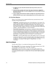
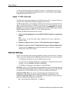
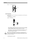
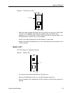
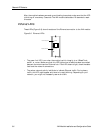
Figure 3-1 C1 Serial Passthrough Port
Set DIP Switches
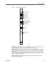
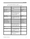
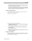
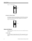
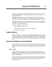
The DIP switches (Figure 3-2) must be set to the correct positions for the INA module to
operate properly.
1. Set DIP switch 1 to the right.
Figure 3-2 DIP Switches
When DIP switch 1 is set to the right and the INA module is turned on, the console
port is set to 9600bps, 8 data bits, 1 stop bit, no parity, and no flow control. This is
the default setting and is used for connecting the C0 port to a console.
When DIP switch 1 is set to the left, the port settings can be controlled by ComOS.
Use this setting for an external modem that is set up to provide access to the
command line interface, for example.
Note – When you change the position of a DIP switch, you must restart the INA
module for the change to take effect. To reboot, press the recessed reboot button on the
front panel of the module. Pushing this button reboots the router software only and
does not affect voice services.
2. Set DIP switch 2 to the left.
C1 serial port
1210-009
T
O
A
D
M
I
N
DIP switch 2
DIP switch
DIP switch 1
1210-002
C
O
N
S
O
L
E