


9
ENGLISH
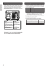
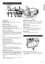
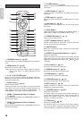
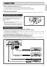
Rear and Terminals
RS-232CDVI-D INRGB IN
EXT.INT.
IN
OUT
OFF ON
1
2
TRIG. LIGHT
REMOTE
VIDEO IN
S-VIDEO IN COMPONENT VIDEO IN 1 COMPONENT VIDEO IN 2
YP
B
/C
B
P
R
/C
R
YP
B
/C
B
P
R
/C
R
1
11 9 8 610
11
12
5
2 3 4
10
10
7
❖ Terminals
z VIDEO IN jack
Connect to the video (composite) output of a video device.
x S-VIDEO IN jack
Connect to the S-video output of a video device.
c COMPONENT VIDEO IN 1 & 2 jacks
Jacks 1 and 2 have each Y, P
B
/C
B
and P
R
/C
R
jacks.
Connect to the component video output of a video device, AV
amp/processor, DVD player, etc.
v TRIG. 1 (TRIGGER 1) jack
Use to control an external unit from this projector by
interlocking the external unit to power ON/OFF (standby) on
this projector. The TRIG. 1 jack outputs 0 V when the projector
is on standby and 12 V when POWER button is in the on
position.
Note:
To connect with external devices, use an ordinal 35mm mini-
plug (mono) cable with attaching the supplied ferrite core.
b LIGHT ON/OFF switch
Switches the terminal lamps on/off.
n TRIG. 2 (TRIGGER 2) jack
The TRIG. 2 jack outputs 12 V in each aspect ratio mode (Full,
Normal, Zoom or Through). For setting instructions, see “Trigger
2” (
☞
pg. 33).
Notes:
• Do not use the TRIG. 1 or 2 jack for power supply.
• To connect with external devices, use an ordinal 35mm mini-
plug (mono) cable with attaching the supplied ferrite core.
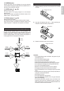
m REMOTE IN / OUT jacks
Use to control this projector when combined with Marantz
products into a system. Connect the REMOTE CONTROL OUT
of the other Marantz product to the REMOTE CONTROL IN of
this projector and the REMOTE CONTROL IN of this other
Marantz product to the REMOTE CONTROL OUT of this
projector.
Note:
Use the included bus control adapter cable to connect this
projector to other Marantz products.
, REMOTE switch (INT. / EXT.)
Set to “EXT.” to control this projector from another connected
Marantz product, whereas set to “INT.” to control this
projector and other connected products from this projector.
. RS-232C port
This is the control terminal for custom installers.
⁄0 DVI-D IN jack
Connect to the RGB digital output of a video device or PC.
Note: When using the DVI-D IN jack, operate the projector
as explained in the precautions on pg. 16.
⁄1 RGB IN jack
Connect to the RGB output of a video device or PC.
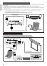
!3 Screw holes for ceiling mount kit
Use to hang the projector from a ceiling. To hang the projector
from a ceiling, contact your nearest Marantz Authorized Dealer
or Service Center.
13
Bottom
Lamp cover
Lamp cover
securing screw
IR sensor
Terminals